286 Keysight EXG and MXG X-Series Signal Generators User’s Guide
Using Custom Digital Modulation for N5172B/82B with Option 431 and 653/655/656/657
Using the Arbitrary Waveform Generator
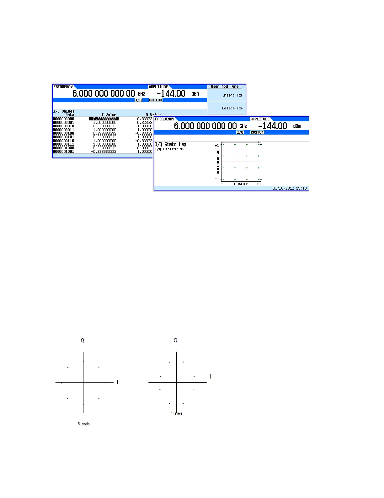
Figure 9-26 shows the X-Series setup and the I/Q display.
Figure 9-26 Custom Modulation and I/Q Display
Hints for Constructing Modulations
— The map is limited to 16 total signal levels for I and Q combined. The readout on the right-hand
side of the table tracks the number of I and Q levels utilized. Levels are I or Q values. Figure 9-27
shows an 8PSK signal built in two different ways. The 8PSK signal in Figure 9-27 utilizes five of
the available sixteen I/Q values on the left, and utilizes four of the available sixteen I/Q values on
the right.
— Following this example, the real-time I/Q baseband generator supports a symmetric 256QAM
constellation but not an asymmetric 256QAM constellation, since the asymmetry requires more
than sixteen I/Q values.
— The levels do not have to be equally spaced or symmetric in the I/Q plane. For example, the
16QAM modulations shown in Figure 9-28 are both possible.
Figure 9-27 8PSK Signal Built Two Ways