306 Keysight EXG and MXG X-Series Signal Generators User’s Guide
Using Custom Digital Modulation for N5172B/82B with Option 431 and 653/655/656/657
Differential Encoding
Entering a value of +1 will cause a 1–state forward transition through the I/Q State Map, as shown
in the following illustration.
As an example, consider the following data/symbol table offset values.
The following I/Q State Map illustrations show all of the possible state
transitions using a particular symbol table offset value. The actual state–
to–state transition would depend upon the state in which the modulation
had started.
Table 9-2
Data Offset Value
00000000 +1
00000001 –1
00000010 +2
00000011 0
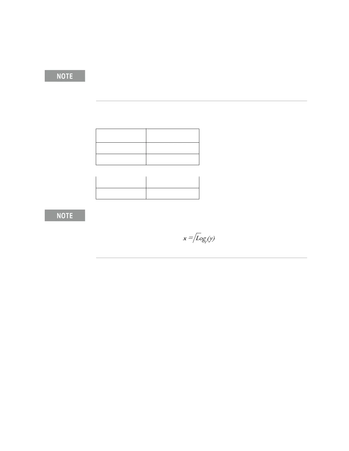
The number of bits per symbol can be expressed using the following
formula. Because the equation is a ceiling function, if the value of x
contains a fraction, x is rounded up to the next whole number.
Where
x = bits per symbol, and y = the number of differential states.