Keysight EXG and MXG X-Series Signal Generators User’s Guide 437
Using the N5102A Digital Signal Interface Module for N5172B/82B with Option 003/004 and
653/655/656/657
Operating the N5102A Module in Output Mode
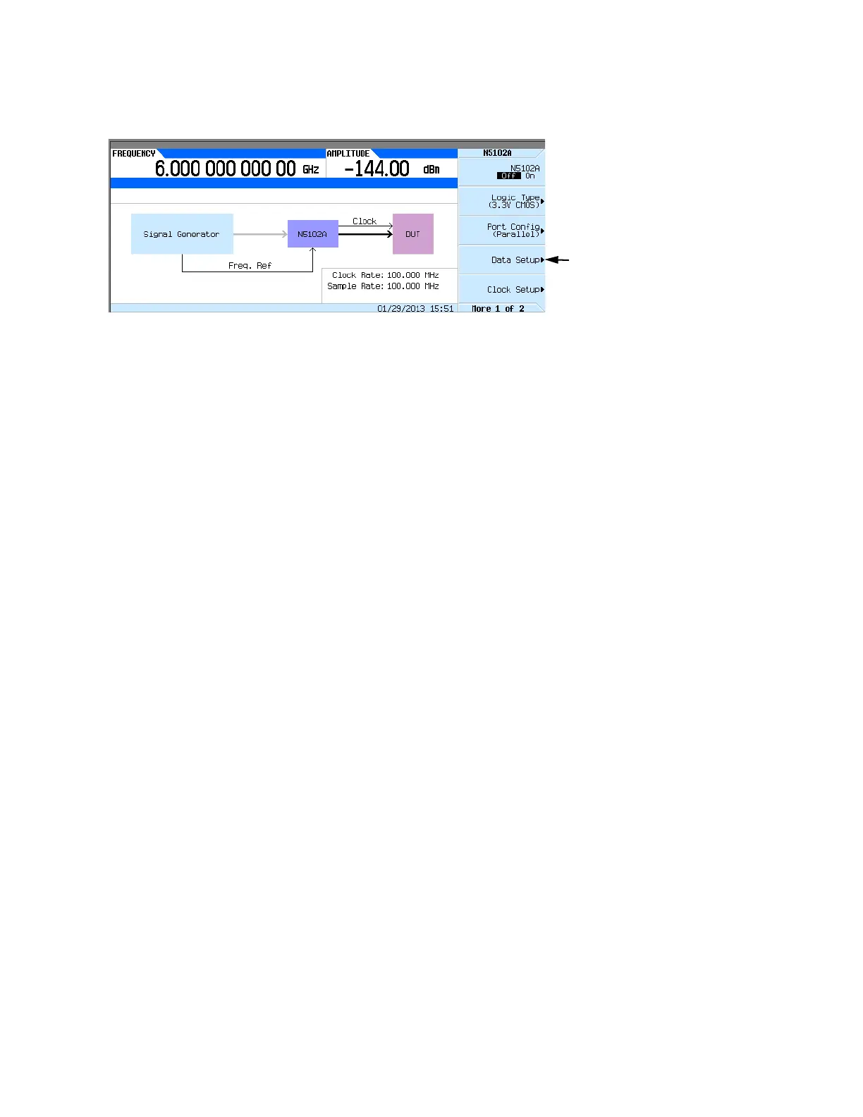
Figure 17-12 Data Setup Menu Location
This softkey menu accesses the various parameters that govern the data received by the
device under test. The status area of the display shows the number of data lines used for both
I and Q along with the clock position relative to the data. When the port configuration is
parallel or parallel interleaved, the number of data lines indicated is equivalent to the word
(sample) size. When the port configuration is serial, the display will show that only one I and
one Q data line is being used along with the frame marker that delineates the beginning of a
sample. Figure 17-13 shows the data setup menu structure.
Accesses the Data Setup menu