46
TOS3200
Connecting the EUT
Connecting the Test lead (TL21-TOS) (Cont’d)
The test lead connection varies depending on the type of TC to be measured and the EUT
class.
Table 4-1 Test lead connections for the type of TC measurement
Test lead A: Test lead connected to measurement terminal A
Test lead B: Test lead connected to measurement terminal B
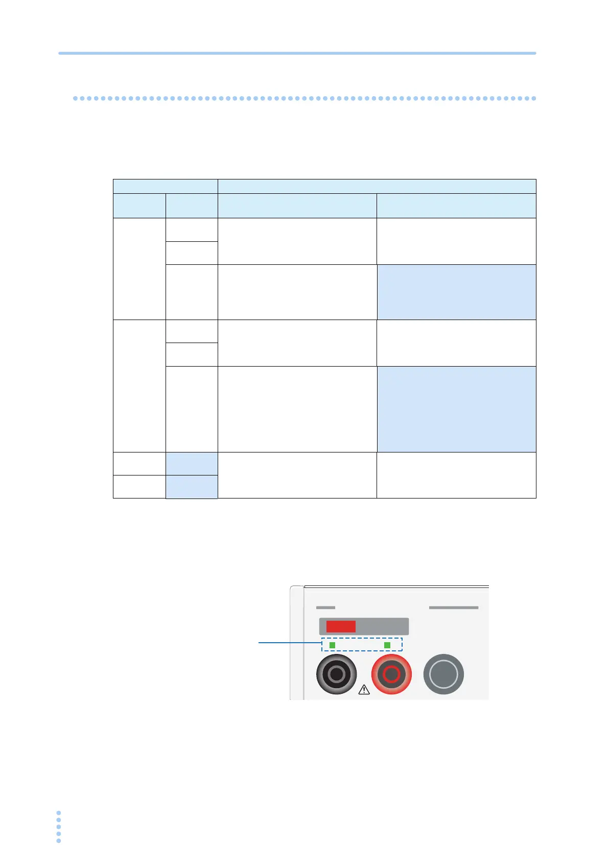
If you select the PROBE item in the TC measurement screen (TC1/2), the LEDs located
above the measurement terminals will illuminate for those that require the test leads to be
connected.
Fig. 4-6 LED connection indications
Setting Connection destination of the test lead
PROBE COND
Class I equipment
Class 0I equipment
Class II equipment
E
NCPE
NORM
Connect test lead A to a part of the enclo-
sure that is not connected to the protective
ground [Connection a of Fig. 4-7].
Connect test lead A to the enclosure.
FLT
NEU
FLTPE
Connect test lead A to a part of the enclo-
sure that is not connected to the protective
ground [Connection a of Fig. 4-7]
or a part that is connected to the protective
ground.
ENCENC
NORM
Connect test leads A and B to parts of the
enclosure that is not connected to the pro-
tective ground (two isolated locations)
[Connection b of Fig. 4-7].
Connect test leads A and B to the enclo-
sure (two isolated locations).
FLT
NEU
FLTPE
Connect test leads A and B to parts of the
enclosure that is not connected to the pro-
tective ground (two isolated locations)
[Connection b of Fig. 4-7]
or to a part that is not connected to the
protective ground and a part that is con-
nected to the protective ground [Connec-
tion c of Fig. 4-7].
ENCLIV
Connect test lead A to a part of the enclo-
sure that is not connected to the protective
ground [Connection a of Fig. 4-7].
Connect test lead A to the enclosure.
E
NCNEU
AB
DANGER
LEAKAGE CURRENT
CAT II
REMOTE
Connect a test lead to
the measurement
terminal for which the
LED is illuminated.
 Loading...


