Kollmorgen - December 2011 83
MMC Smart Drive Hardware Manual - 230V 1/3 PHASE MMC SMART DRIVE
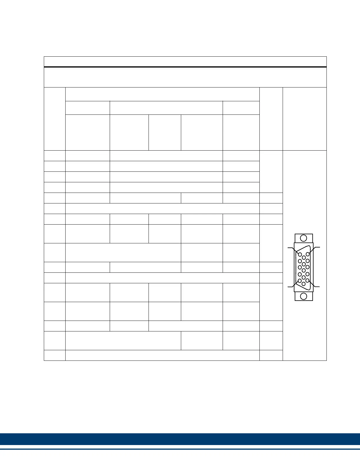
Table 5-12: Pin Assignments for Feedback Connector (F1)
Encoder/Resolver Pin Assignments for Motor Feedback 15 Pin Connector (F1)
230V Single Phase (500W, 1kW, 2kW)
Pin
Feedback Device
In/
Out
Connector
Pinout
Sinewave Encoder
Digital
Incremental
Encoder
Stegmann
Hiperface
Endat
a
BISS
a,b,c
SSI
a,d
a. Available on Digital Interfaced MMC-SD only
b. Not on all Part Numbers. See section 5.3.2 on page 119 for details
c. Cos, Cos/, Sine, Sine/ Not Used for BiSS Encoder
d. For future use
Heidenhain
Sincoder
Resolver
e
e. Requires installation of optional resolver board.
1 A1 Cos Cos+
In
15-pin
Female
HD D-Sub
2 A1/ Cos/ Cos-
3 B1 Sine Sin+
4 B1/ Sine/ Sin-
5 I1 RS-485 Data+ Ref Mark Carrier+
Note
f
f. Pins 5 and 10 are In/Out for Stegmann Hiperface and Endat; Inputs for Digital Incremental, SSI, BiSS,
Heidenhain Sincoder; and Outputs for Resolver
6 Common In/Out
7 N/U +9V Source N/U N/U N/U Out
8
Commutation
Track S3
N/U N/U N/U N/U
In
9 N/U
Commuta-
tion Cos+
N/U
10 I1/ RS-485 Data- Ref Mark/ Carrier-
Note
f
11 Temperature In
12
Commutation
Track S1
N/U
RS-485
Clock+
Commuta-
tion Sin+
N/U
In
g
g. Pins 12 and 13 are Outputs for ENDAT, SSI, and BiSS
13
Commutation
Track S2
N/U
RS-485
Clock-
Commuta-
tion Sin-
N/U
14 +5V Source N/U +5V Source N/U Out
15 N/U
Commuta-
tion Cos-
N/U In
Shell Shield N/A
5
1
15
11
 Loading...