84 Kollmorgen - December 2011
MMC Smart Drive Hardware Manual - 230V 1/3 PHASE MMC SMART DRIVE
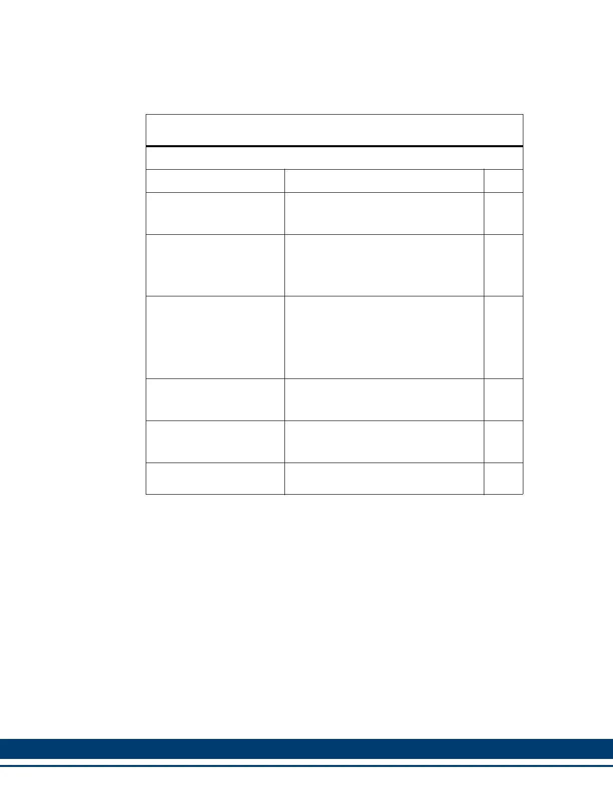
Table 5-13: Pin Description for Feedback Connector (F2)
(Digital Interfaced MMC-SD Only)
F2 Feedback Signals
Signal Type Notes Pins
Incremental Encoder Input Differential A quad B encoder signals.
1,2,
3, 4,
5, 10
Motor Commutation
Hall Sensor Inputs
Hall-device input signals that are used to
initialize the motor commutation angle.
They consist of a 74HC14 input with a
10μs filter and a 1K pull-up to +5V. Shared
with F1.
8, 12,
13
Temperature Input
Thermostat (normally-closed) or Ther-
mistor (Phillips KTY84-130 PTC or equiva-
lent recommended) input for detecting over
temperature conditions within the motor. If
a thermostat is used, connect one side to
0V, and the other side to the Temperature
Input (pin 11).
11
+5V Encoder Power Outputs
Regulated +5VDC for powering the at-
tached encoder (F1 pin 14 + F2 pin 14 =
500ma max).
14
+9V Encoder Power Outputs
Regulated +9VDC for powering the at-
tached encoder (F1 pin 7 + F2 pin 7 =
150ma max).
7
Signal and Power Common
Return path for feedback signals and pow-
er supplies (+5V and 9 V).
6
 Loading...