LDI Intellectual Property.
Not for secondary distribution or replication, in part or entirety.
DIGISONDE-4D
SYSTEM MANUAL
VERSION 1.2.11
SECTION 5 - SYSTEM SOFTWARE – ANNEX A 5-49
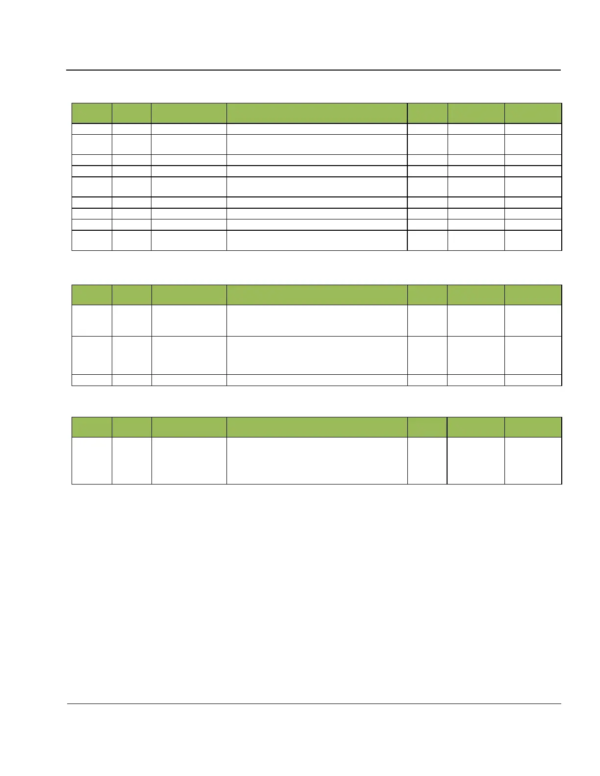
Table 5A- 32: Hardware Sensors Payload Structure
Schedule Number (0 means manual start of sound-
ing)
BIT Program Specification (see Table 5A- 6)
Static sensor data collected in digital and analog
channels
Sensor data collected in Case #0 of BIT
Sensor data collected in Case #1 of BIT
Sensor data collected in Case #2 of BIT
Sensor data collected in Case #3 of BIT
Table 5A- 33 Static Sensor Data Collected in BIT
Status of 32 digital sensors A, B, C, and D
(
Table 5A- 35)
Status of static analog sensors (Table 5A- 36)
For each sensor, the maximum sensor value over a set
of collected samples is obtained by DESC to report
here
Table 5A- 34: Dynamic sensor data collected in BIT case 0, 1, 2, and 3
Status of 8 dynamic analog sensors
(Table 5A- 37)
For each sensor, the maximum sensor value over a set
of collected samples is obtained by DESC to report
here
 Loading...