LDI Intellectual Property.
Not for secondary distribution or replication, in part or entirety.
DIGISONDE-4D
SYSTEM MANUAL
VERSION 1.2.11
2-20 SECTION 2 - INSTALLATION, SETTING UP AND FIELD VALIDATION
VERIFICATION OF CABLES AND ANTENNA PRE-AMPLIFIERS VIA EXTERNAL LOOPBACK
2:68. Cable and antenna pre-amplifier verification must be performed at system installation to identify and
correct phase errors, and may be repeated periodically to see if corrections are necessary.
Matching Antenna Cable Lengths
2:69. Ideally all the antenna cables should be matched to 6 inches or 20 cm. They can be matched using ei-
ther physical or electrical techniques. . To match cable lengths electrically, use a Time Domain Reflectome-
ter (TDR). The far ends of the cables should either all be either open or shorted. Be aware if the acquired
cables are from different manufacturers or lot numbers cables may have significantly different physical
length when matched electrically (most likely due to differences in dielectric when manufactured).
FIELD VALIDATION OF INSTALLED ANTENNAS AND CABLES
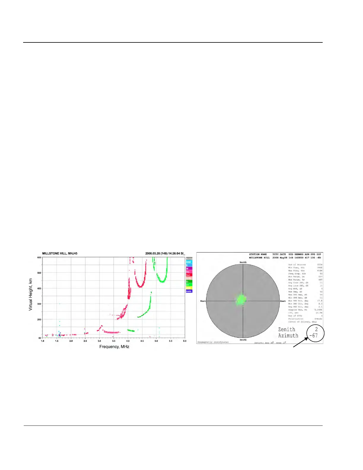
2:70. With a quiet ionosphere, skymaps and RSF ionograms should generally appear to be overhead. Figure
2-9 is a sample of the skymap showing ionospheric tilt close to 0 (zenith angle of 2°, azimuth angle is irrele-
vant).
2:71. After verifying that the ionograms and skymaps generally appear to be overhead, add two test cables to
artificially tilt antenna array as follows. For a four antenna array, 60 meters on a side, temporarily add a 18
meter extension to an outer antenna cable and temporarily add a 6 meter extension to the center antenna ca-
ble. This will tilt the antenna beam approximately 20 degrees in the direction away from outer antenna
which has the extra cable length. Figure 2-12 and show extension cable connections and expected tilt of the
antenna beam for standard and mirror antenna layouts. Such a large artificial tilt should be clearly evident
on both the skymap and ionogram data.
Figure 2-9: Ionogram (a) and Skymap (b) for Almost Overhead Ionosphere (No Test Cables Inserted)
 Loading...