LDI Intellectual Property.
Not for secondary distribution or replication, in part or entirety.
DIGISONDE-4D
SYSTEM MANUAL
VERSION 1.2.11
SECTION 2 - INSTALLATION, SETTING UP AND FIELD VALIDATION 2-21
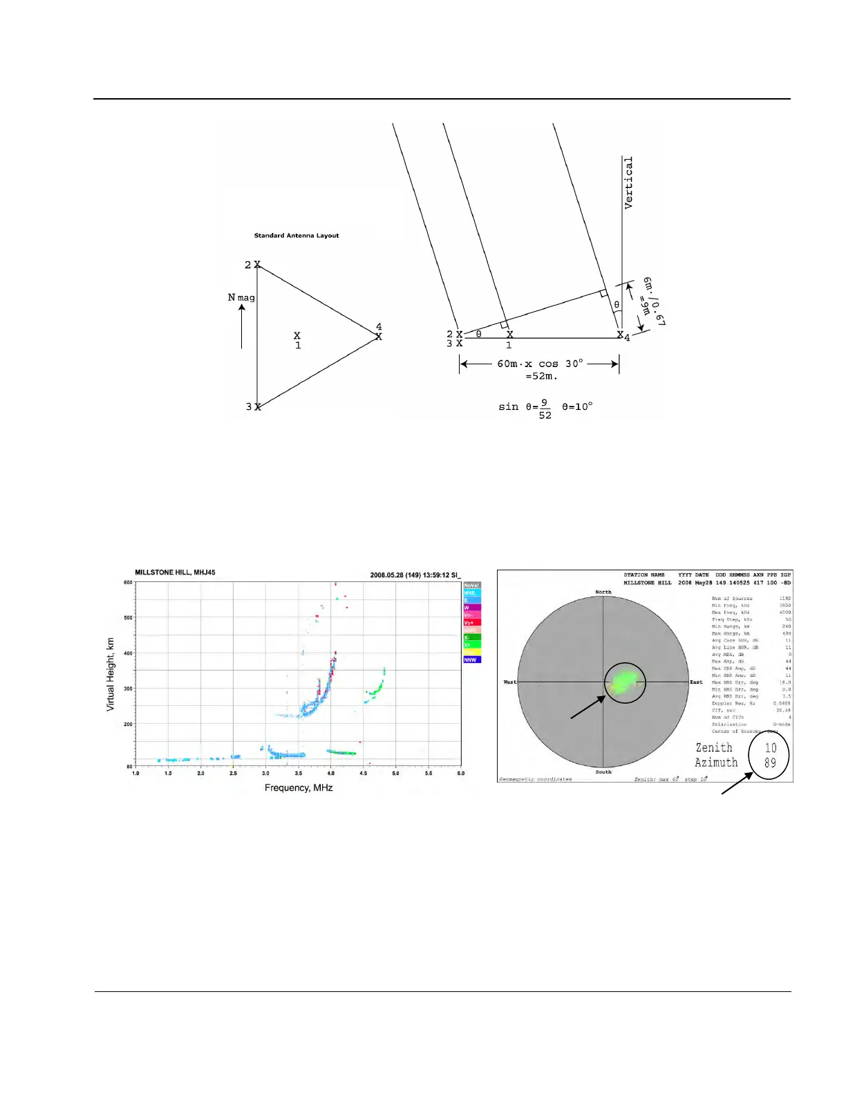
Figure 2-10: Rx Antenna Calibration Setup with Added Test Cable Segments
(Standard Antenna Layout)
2:72. Example ionogram and skymap obtained in the tilted antenna array configuration are shown in Figure
2-11, where tilt is accomplished in the mirror antenna configuration, thus corresponding to the apparent
eastward direction of the echoes.
Figure 2-11: Example Ionogram (a) and Skymap (b) Obtained with Extension Cables Inserted
(Skymap shows apparent shift of 10° zenith to East (azimuth 89°),
and ionogram echoes are tagged as oblique East)
POST INSTALLATION CHECKS
2:73. At this stage it is recommended that the operator tests the system by modifying and running measure-
ment programs as outlined in Section 3 (Operating Modes and Instructions) of this manual.
 Loading...