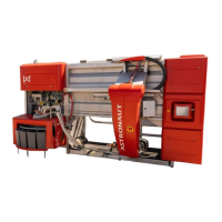
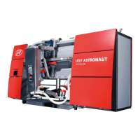
System controls
Chapter 2 - page 2
M-HE.002.1003
Use the STOP-button (10) only in case of an emergency.If power supply to the robot should be switched off, e.g.
for maintenance, use the "ON/OFF" switch located behind the multiple function control box (B, figure 6.16).
2.1.2 POWER lamp (2)
This lamp indicates if the robot is being supplied with power.
2.1.3 ALARM lamp (3)
This lamp starts burning in case the robot generates an alarm.
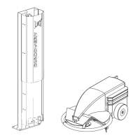
2.1.4 Control function keys B1 - B8 (4)
These keys (figure 2.2) control the operation listed below. Depress the
key once to turn on and again to turn off.
(B1) Pipeline blowing
(B2) Milk separation
(B3) Feeding
(B4) RESET
(B5) Milk pump
(B6) Cleaning of separation line
(B7) Out-of-operation + indication
(B8) No function
2.1.5 Display (5)
The display (figure 2.1) shows the available cow data, which can be retrieved from the memory by means of the
data function keys.
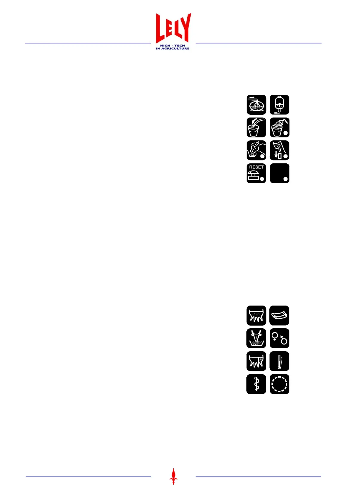
2.1.6 Data function keys G1 - G8 (6)
By means of these keys (figure 2.3) the following data is retrieved and/
or registered:
(G1) Milk data
(G2) Feed data
(G3) Conductivity data
(G4) Disease codes
(G5) Cow data
(G6) Calendar data
(G7) Temperature data
(G8) Reset
Underneath each key you will find a number of displays with relevant data. Some of this data can be changed by
means of the control panel. In section 2.4 ’DATA FUNCTIONS’ a description of the screens is given.
B1
B2
B3
B4
B5
B6
B7
B8
Figure 2.2 Control function keys (B)
Figure 2.3 Data function keys (G)
G1
G2
G3
G4
G5
G6
G7
G8