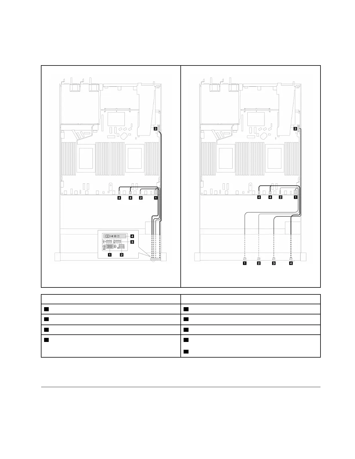
• The illustrations show the cabling scenario for server models with 2.5-inch and 3.5-inch front drive bays.
Location of each connector on the front of the server varies by models. For detailed locations of front I/O
components for different models, see
“Front view” on page 19 and “Front I/O module” on page 33.
Figure 229. Cable routing for a front I/O module on 2.5''
chassis
Figure 230. Cable routing for the front I/O module on 3.5''
chassis
From To
1 VGA connector 1 VGA connector
2 External LCD diagnostics handset connector
Note
2 External LCD diagnostics handset connector
3 Front USB connector 3 Front USB connector
4 Front operator panel
4 Left: front panel connector
4 Right: front panel LCD connector
Note: The external LCD connector is not available on certain front I/O modules of 10 x 2.5-inch server
models.
Intrusion switch
Use the section to understand the cable routing for the intrusion switch.
Chapter 6. Internal cable routing 263

 Loading...


