Chapter 5 System Operation
890 USE 120 00 87
Description of the restart lock -AS-, continued
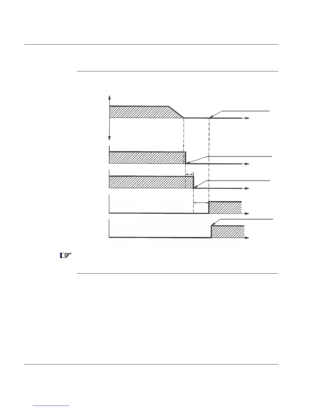
Signal diagram
(sequence)
Note: Restart lock input must not be activated when the drive is enabled. The
diagram above must be respected.
terminal Analog1 +/-
terminal Enable
terminal Brake+
terminal KSI+
terminal KSO1/2
internal setpoint lock
motor locked by controller
motor blocked mechanically
accessible zone
t
t
t
t
t
≤1s
>0.2s
+
0
-
+24Vdc
0
+24Vdc
0
+24Vdc
0
1
0
setpoint
(input)
Enable
(input)
brake
(output)
restart
lock
(input)
supervisory
contact
(output)