121
Electrical Specifications - Signal, continued
Encoder Output
(Incremental
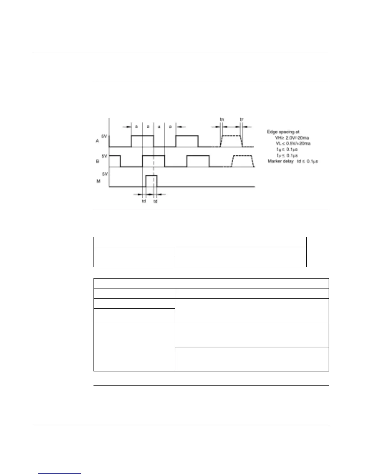
Format) Timing
Diagram
The following diagram shows the timing for the encoder output (incremental format).
Encoder Output
(SSI Format)
Specifications
Table
The following two tables provide 17D encoder output (in SSI format) specifications
Continued on next page
≥
0.2 µS
ENCODER OUTPUT (SSI FORMAT) - ELECTRICAL
Channels Data and Clock
Type Differential, RS-485 compliant
ENCODER OUTPUT - SSI FORMATTING
Primary Feedback Type Possible Emulations
Resolver Single-turn SSI - 12 upper bits set to 0, 12 lower bits for
position within one turn. Configurable for Gray or binary
code.
Sin-Cos (single-turn)
Sin-Cos Single-turn SSI - 12 upper bits set to 0, 12 lower bits for
position within one turn (SSIMODE 0). Configurable for
Gray or binary code.
Multi-turn SSI - 12 upper bits for turns count, 12 lower bits
for position within one turn (SSIMODE 1). Configurable for
Gray or binary code.


 To Next Page