Chapter 5 System Operation
890 USE 120 00 91
Description of the restart lock -AS-, continued
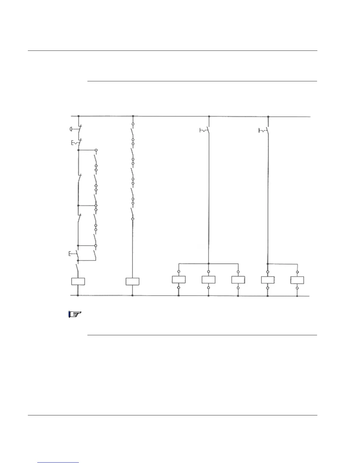
Control circuit
example
Note: - Servo drives 1, 2 and 3 inside the enclosure 1 with door contact S1
- Servo drives 4 and 5 inside the enclosure 2 with door contact S2
+24Vdc
Emerg.
OFF
OFF
S1
S2
ON
K1
0V
KSO1
KSO2
KSO1
drive 2
drive 1
KSO2
KSO1
drive 3
KSO2
KSO1
drive 4
KSO2
KSO1
drive 5
KSO2
K1
K2
Fault RA/RB drive 2
Fault RA/RB drive 1
Fault RA/RB drive 3
Fault RA/RB drive 4
Fault RA/RB drive 5
lock
drives
1-2-3
lock
drives
4-5
drive 1 drive 2 drive 3 drive 4 drive 5auxiliary contactormains contactor
KSI+
KSI-
KSI+
KSI-
KSI+
KSI-
KSI+
KSI-
KSI+
KSI-
Enclosure
contacts
(closed doors)
K2


 To Next Page