66
Signal Wiring, continued
SSI Encoder
emulation
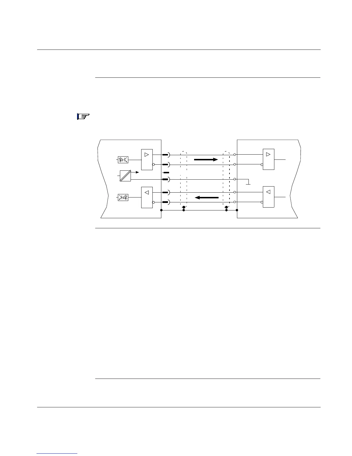
The following diagram shows the connections between a motion controller and the
17D drive.
Note: The drivers are supplied from an internal supply voltage. P
Com
must always
be connected to the controller ground.
SSI Encoder
Output
Functional
Description
The SSI interface is synchronous serial absolute-encoder emulation. The position
of the servo motor shaft is calculated using the cyclic-absolute signals from the
resolver or encoder. This calculation is then used to generate a synchronous,
serial, cyclic-absolute 12-bit information output that is compatible with the data
format of normal commercial SSI absolute encoders. A total of 24 bits are
transmitted as follows:
l The upper 12 bits contain the number of turns (multi-turns) or are fixed at zero
(single turn)
l The lower 12 bits contain the cyclic absolute position information.
The signal sequence can be output in either:
l Gray code
l Binary code
The count increments positively when the motor shaft is rotating clockwise (when
viewed from the shaft end).
Continued on next page
=
=
Lexium 17D
RS-485
RS-485
5V
X5
6
7
4
8
1
5
Data -
Data +
Clock +
P
Com
Motion Controller
RS-485
RS-485
Gnd
Clock -
=
=
Nc
Data
Clock