65
Signal Wiring, continued
Incremental
Encoder
Emulation
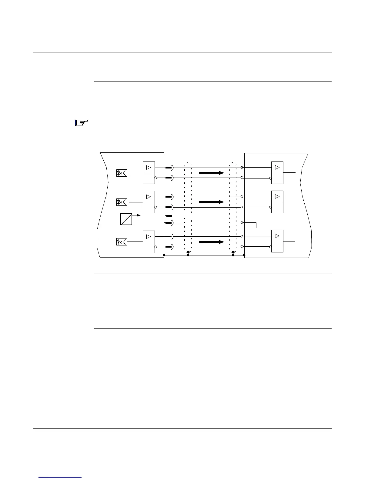
The following diagram shows the incremental encoder output connections between
the 17D drive and the motion controller.
Note: The drivers are supplied from an internal supply voltage.
P
Com
must always be connected to the controller ground.
Use a cable with twisted pairs and shield (max. length: 10m.)
Incremental
Encoder Output
Functional
Description
The position of the servo motor shaft is calculated using the cylic-absolute signals
from the resolver or encoder. The calculated position information is used to
generate two incremental-encoder compatible signals (A and B) with a 90° phase
difference and a marker pulse.
Continued on next page
=
=
Lexium 17D
RS-485
RS-485
RS-485
5V
Reserved
X5
5
4
2
3
6
8
1
7
A+
A-
M-
M+
B+
B-
P
Com
Motion Controller
RS-485
RS-485
RS-485
Gnd
Chan A
Marker
Chan B