70
Analog I/O Connection
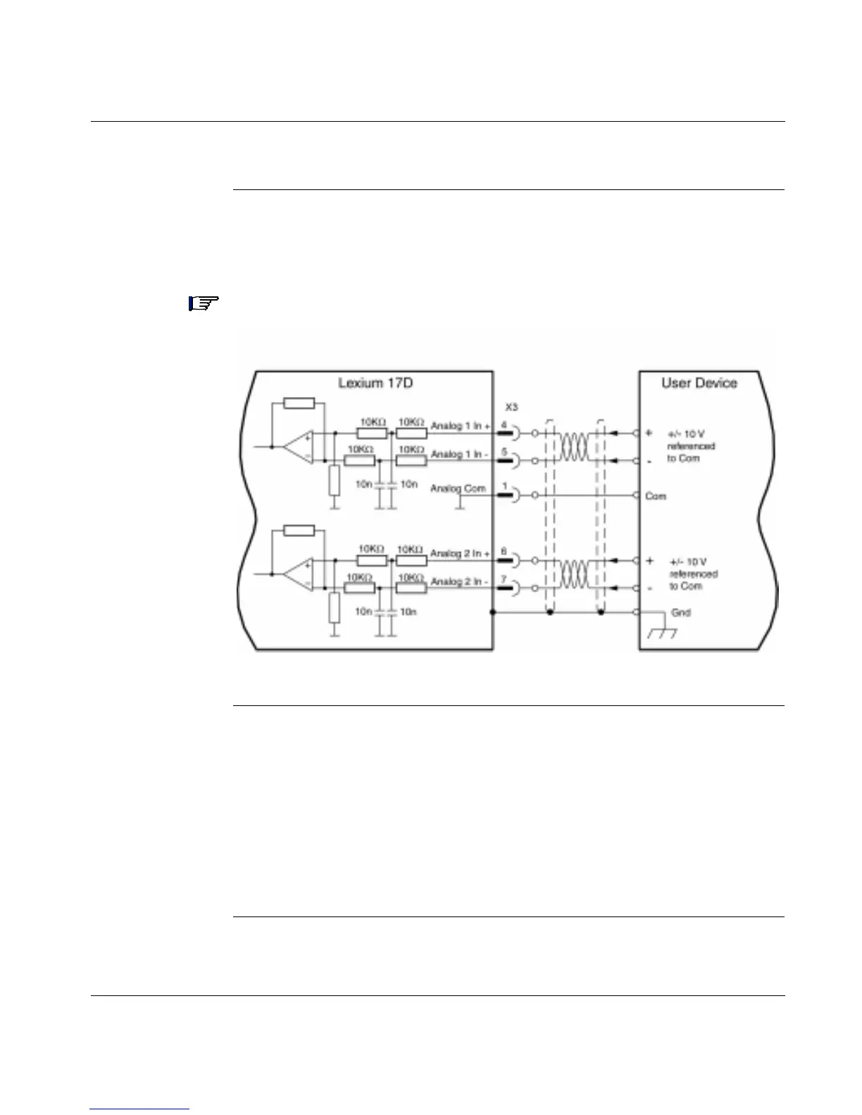
Analog Inputs The following diagram shows the connections between the two fully programmable,
differential analog inputs on the 17D drive and a user device. (Refer to the list of
pre-programmed functions contained in the UniLink online help.)
Note: The Analog Com must always be connected to the user device Com as a
ground reference.
Servo Motor
Rotation
Direction
The standard setting for direction of positive rotation of the servo motor shaft is
clockwise (looking at the shaft end) and is achieved as follows:
l Positive voltage on connector X3, between terminals 4 (+) and 5 (-), or
l Positive voltage on connector X3, between terminals 6 (+) and 7 (-)
To reverse the direction of rotation, change the ROT. DIRECTION parameter in the
"Speed controller" window; this window is accessed via the UniLink Configuration
software.
Continued on next page