67
Signal Wiring, continued
Diagram of
master-slave
operation
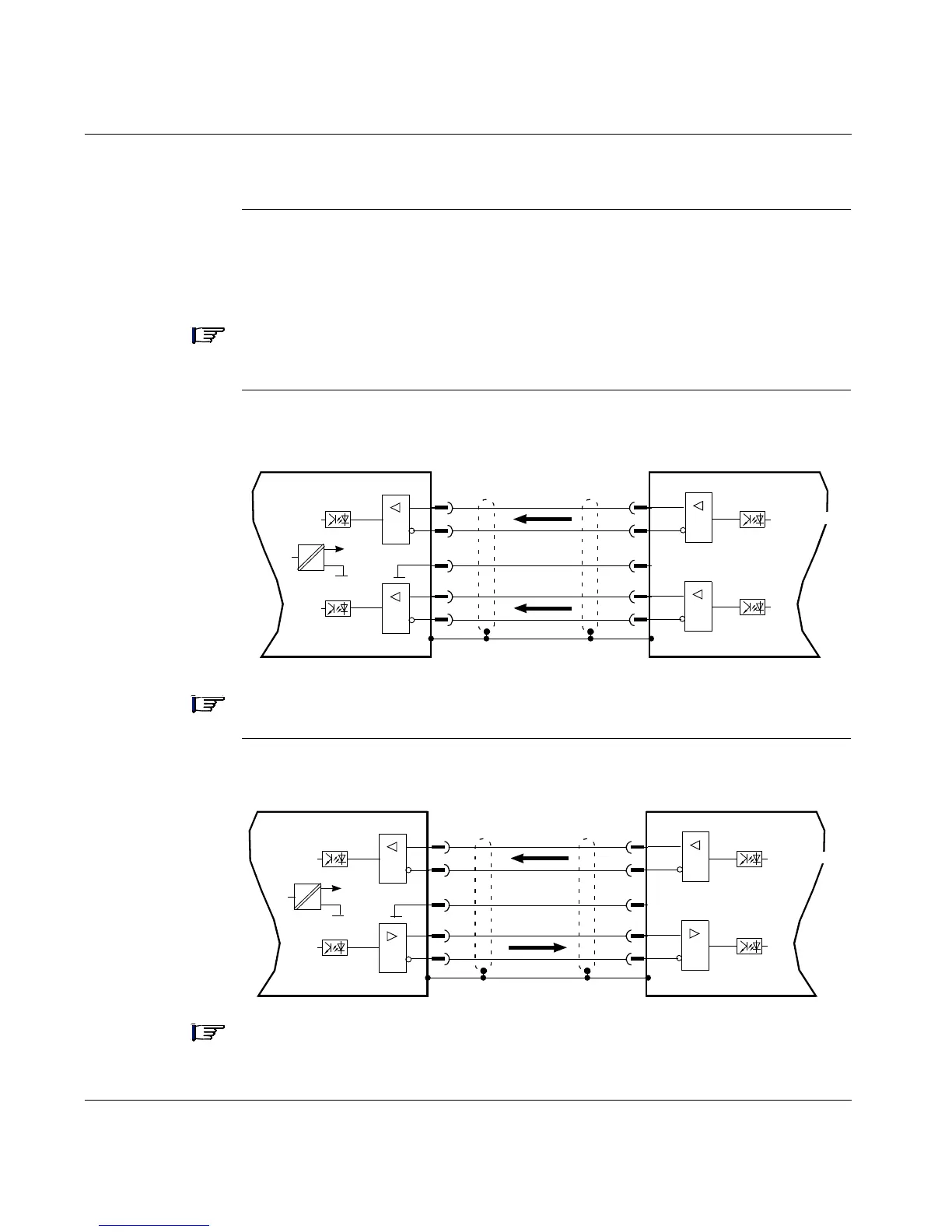
The encoder interface can be used to link one or more 17D HP drives together in a
master-slave operation, as shown in the following diagram. The UniLink software
allows you to setup the parameters for the slave drive(s).
Note: In this configuration, the analog setpoint inputs are disabled, a Analog Com
and I/O Com (connector X3) must be connected together.
Incremental
encoder
emulation
Note: Up to 16 slaves drives can be controlled by the master drive.
SSI encoder
emulation
Note: Only one slave drive can be controlled by the master drive.
=
=
Lexium 17D
RS-485
+5 V
X5
5
4
6
1
7
A -
A +
B+
P
Com
Lexium 17D
RS-485
RS-485
B-
Master
X5
5
4
6
1
7
RS-485
PCom
Chan A
Chan B
Slave
=
=
=
Lexium 17D
RS-485
+5 V
X5
6
7
5
1
4
Data -
Data +
CLK+
P
Com
Lexium 17D
RS-485
RS-485
CLK-
Master
X5
6
7
5
1
4
RS-485
PCom
Chan A
Chan B
Slave
=