142
Wiring a 17D Drive to a MOT 201 Motion Module, continued
MOT 201
Encoder Wiring
Diagram:
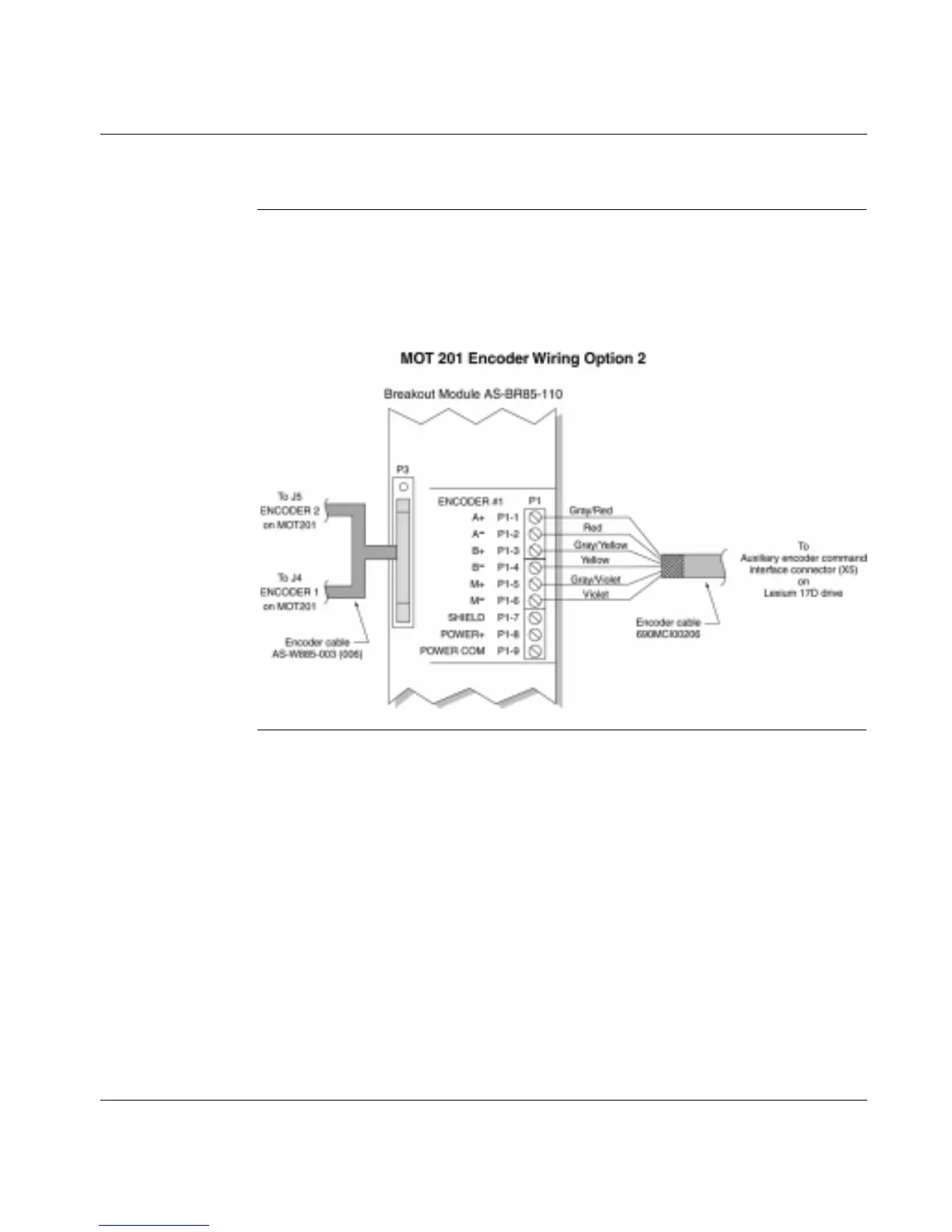
Option 2
The following diagram shows how the AS-BR85-110 breakout module facilitates
encoder wiring between a MOT 201 motion module and an Lexium 17D drive. At
one end, the MOT J5 and J4 connectors are plugged into the breakout module P3
connector. At the other end, the breakout module P1 connector is wired to the
drive’s auxiliary encoder command Interface connector.
 Loading...