58
Power Wiring, continued
Servo Motor
Holding-Brake
Control
Functional
Description
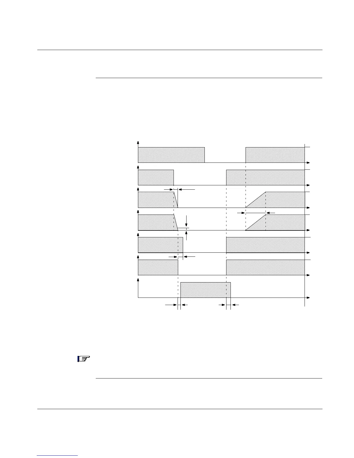
A 24V holding brake in the servo motor is controlled directly by the 17D drive
through software-selectable BRAKE parameter settings. The time and functional
relationships between the ENABLE signal, speed setpoint, speed and braking force
are shown in the following diagram.
.
During the fixed ENABLE delay time of 100 ms, the internal speed setpoint of the
drive is internally driven down a 10 ms ramp to 0 V. The 3 % region of actual speed
is scaled to V
LIM
.
Note: The set and release times of the holding brake vary with the servo motor and
thus must be considered when setting parameters.
Continued on next page
10ms
100ms
t
SET t RELEASE
3%
Ramp +
t
t
t
t
t
t
t
V
V
V
S
V
V
F
Speed
Setpoint
Input
ENABLE
Input
Internal
Speed
Setpoint
Actual
Speed
ENABLE
Internal
BRAKE
Output
Bracking
Force