3
About this User Guide, continued
How this User
Guide Is
Organized,
continued
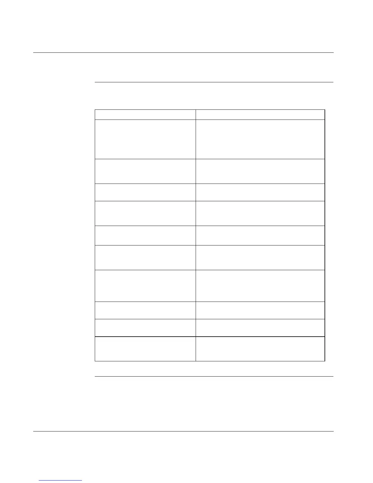
Chapter/Appendix Description
Chapter 4
Wiring and I/O
Wiring diagrams for the power connections and
wiring diagrams and descriptions for all signal
wiring connections — encoder, resolver, analog
I/O, discrete I/O, and serial communications
cable.
Chapter 5
System Initialization, Commissioning
and Operation
Detailed procedures and associated descriptions
on how to initialize, commission and operate a
typical 17D system.
Chapter 6
Troubleshooting
Description of faults, probable causes and
recommended corrective actions.
Appendix A
Specifications
Specifications for the servo drives, including
general, electrical, signal, and power
specifications.
Appendix B
Parts List
Part numbers related to the 17D servo drive
system.
Appendix C
Drive to Controller Wiring Diagrams
Wiring diagrams that show signal wiring between
a 17D servo drive and MOT 201, Quantum MSx,
B885-11x, and Premium CAY motion modules.
Appendix D
Cable Connection Wiring Diagrams
Procedures and associated diagrams that show
how to wire Sub-D and power cable connectors
as well as the serial communication cable used
with the drive.
Appendix E
Servo Loop Diagrams
Illustrations of the 17D servo drive and single-
axis motion module servo loops.
Appendix F
Expansion Options
Description and procedure for using the I/O
expansion card with the drive.
Appendix G
External Regen Resistor Sizing
Description and procedure for determining the
power dissipation requirement for the external
Regen resistor.
 Loading...