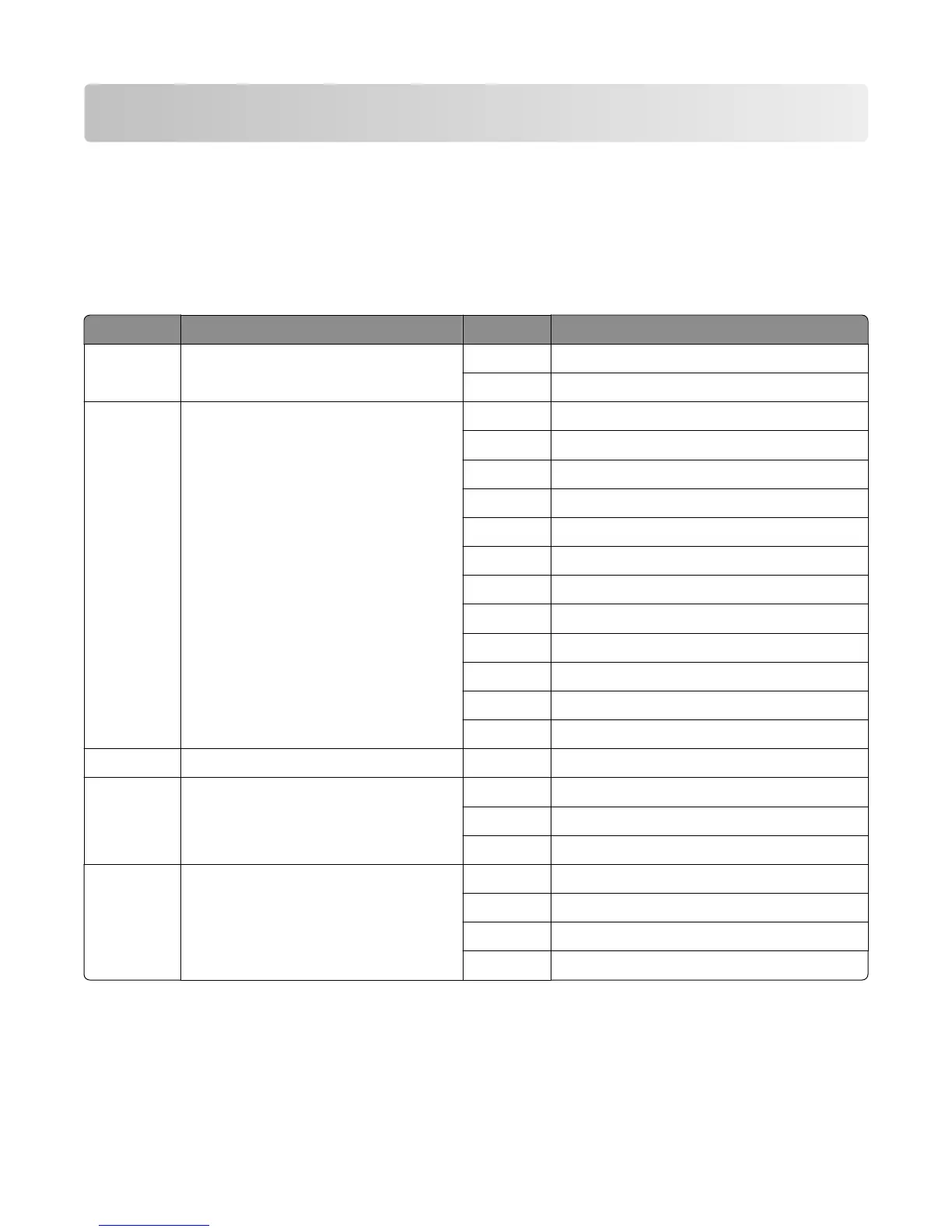
Component locations
Connectors
See the wiring diagram section at the end of this manual.
Controller board
Connector Connects to Pin no. Signal
J3 MPF pick solenoid 1 S_MPF_PWM*_C
2 +24V_FUSE_A
J9 Cartridge cooling fan/HVPS 1 S_CART_FAN_ENC_C
2 GND
3 S_CART_FAN_C
4 S_HVPS_SERVO_C
5 S_HVPS_TX_ENB*_C
6 S_HVPS_TX_PWM_C
7 S_+24V_SW_C
8 S_HVPS_CHG_C
9 GND
10 S_HVPS_DEV_C
11 S_HVPS_ID_C
12 not used
J13 Control panel USB interface N/A N/A
J18 Rear door interlock sensor 1 RR_DRV_SNS_OUT_C
2 GND
3 S_RR_DRV_LED_C
J20 Sensor (input) 1 S_INPUTSNS*_C
2 GND
3 S_INPUTSNS_LED_C
4 not used
4063
Component locations
515