Gocator Snapshot Sensors: User Manual
Gocator Web Interface • 134
Data Viewer
When the Measure page is active, the data viewer can be used to graphically configure measurement
regions in the 2D or in the 3D views. Measurement regions can also be configured manually in
measurements by entering values into the provided fields (see Regions on page 136).
For information on controls in the data viewer, see Data Viewer Controls on page 102.
For instructions on how to set up measurement regions graphically, Region Definition on page 111.
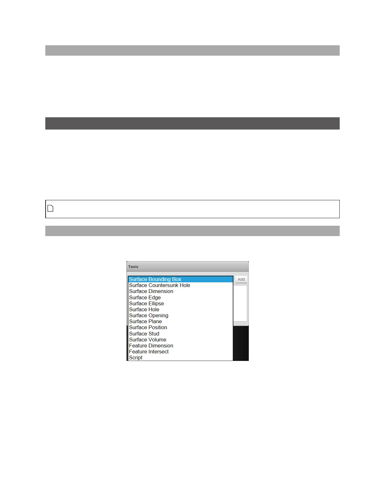
Tools Panel
The Tools panel lets you add, configure, and manage measurement tools. Tools contain related
measurements. For example, the Position tool provides X, Y, and Z position measurements.
Some settings apply to tools, and therefore to all measurements; these settings are found in the
Parameters tab below the list of tools. Other settings apply to specific measurements, and are found in
a Parameters tab below the list of measurements; not all measurements have parameters.
See Surface Measurement on page 189 for information on the measurement tools and their settings.
Tool names in the user interface include the scan mode, but not in the manual. So for example, you
will see "Surface BoundingBox"in the user interface, but simply "BoundingBox" in the manual.
Adding and Configuring a Measurement Tool
Adding a tool adds all of the tool's measurements to the Tools panel. You can then enable and configure
the measurements selectively.
To add and configure a tool:
1. Go to the Scan page by clicking on the Scan icon.
2. Choose Profile or Surface mode in the Scan Mode panel.
If one of these modes is not selected, tools will not be available in the Measure panel.
3. Go to the Measure page by clicking on the Measure icon.
 Loading...