Gocator Snapshot Sensors: User Manual
Getting Started • 23
Installation
The following sections provide grounding, mounting, and orientation information.
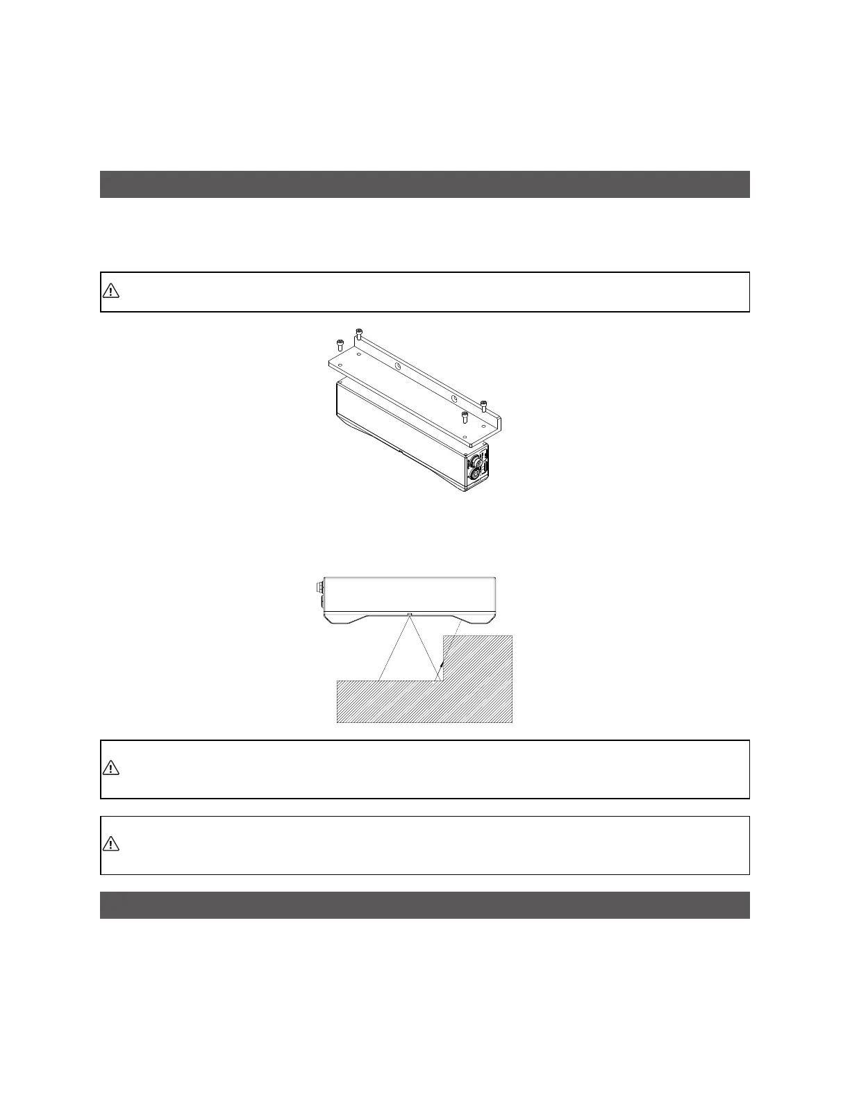
Mounting
Sensors should be mounted using a model-dependent number of screws. Some models also provide the
option to mount using bolts in through-body holes. Refer to the dimension drawings of the sensors in
Specifications on page 519 for the appropriate screw diameter, pitch, and length, and bolt hole diameter.
Proper care should be taken in order to ensure that the internal threads are not damaged from
cross-threading or improper insertion of screws.
With the exception of Gocator 2880, sensors should not be installed near objects that might occlude a
camera's view of the LEDlight pattern. (Gocator 2880 is specifically designed to compensate for
occlusions.)
The sensor must be heat sunk through the frame it is mounted to. When a sensor is properly
heat sunk, the difference between ambient temperature and the temperature reported in the
sensor's health channel is less than 15° C.
Gocator sensors are high-accuracy devices. The temperature of all of its components must be
in equilibrium. When the sensor is powered up, a warm-up time of at least one hour is required
to reach a consistent spread of temperature within the sensor.
Grounding
Components of a Gocator system should be properly grounded.
 Loading...