Gocator Snapshot Sensors: User Manual
Gocator Web Interface • 252
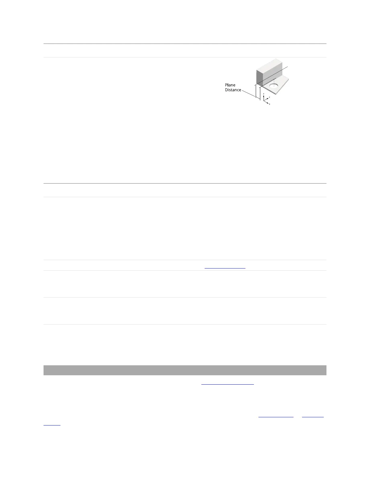
Measurement Illustration
Plane Distance
Point-point: The distance between two point geometric
features. For profile data, the points are projected onto the
XZ plane (always the same as the Distance measurement).
For surface data, the points are projected onto the XY plane.
Point-line: The distance between a point and a line. For
profile data, projected onto the XZ plane (always the same
as the Distance measurement). For surface data, the
distance is projected onto the XY plane.
Point-plane: The distance between a point and a plane. For
profiles, the distance is projected onto the XZ plane (always
the same as the Distance measurement). For surface data,
the distance is projected onto the XY plane.
Parameter Description
Stream The data that the tool will apply measurements to.
In Surface mode, this setting is only displayed when a
section is defined on the surface data.
If you switch from one type of data to another (for example,
from section profile data to surface data), currently set
input features will become invalid, and you will need to
choose features of the correct data type.
Point A point geometric feature generated by another tool.
Reference Feature A point or line geometric feature generated by another tool.
Dimensional measurements are calculated from the
reference feature to the point in the Point setting.
Filters The filters that are applied to measurement values before
they are output. For more information, see Filters on page
143.
Decision The Max and Min settings define the range that determines
whether the measurement tool sends a pass or fail decision
to the output. For more information, see Decisions on page
142.
Parameters
Intersect
The Feature Intersect tool returns the intersection of a line geometric features and a reference line or
plane geometric feature. For line-line intersections, the lines are projected onto the Z = reference Z line
plane for features extracted from a surface, and the intersection of the lines projected onto the Y = 0
plane for features extracted from a profile. The angle measurement between the two lines is also
returned. The lines the tool takes as input are generated by other tools, such as Surface Edge or Surface
Ellipse.
 Loading...