Gocator Snapshot Sensors: User Manual
How Gocator Works • 40
3DData Output
Gocator measures the shape of the object calculated from either dual triangulation or stereo correlation.
The Gocator reports a series of 3D coordinates from the surface of the target in the sensor's field of
view.
Coordinate Systems
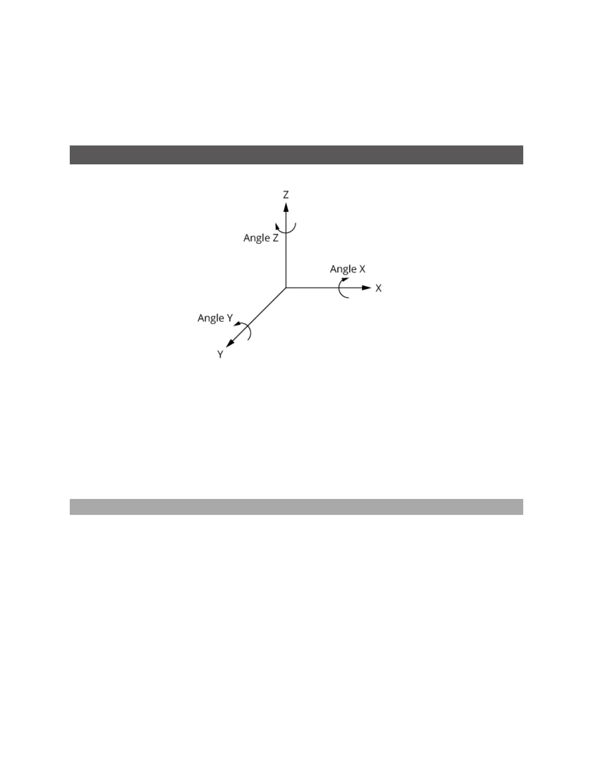
Gocator 3x00 sensors use Cartesian left-hand notation for defining 3D coordinates.
The Z axis represents the sensor's measurement range (MR), where the values increase toward the
sensor. The X axis and Y axis represent the sensor's field of view (FOV).
X offset, Y offset, and Z offset define the translations from the origin.
Rotations are specified based on rotating the target around the X axis (Angle X), followed by rotating
around the Y axis (Angle Y), followed by rotating around the Zaxis.
3D point cloud data is reported in sensor coordinates or system coordinates depending on the
alignment state of the sensor. These coordinate systems are described below.
Sensor Coordinates
Unaligned sensors use the coordinate system shown below.
The measurement range (MR) is along the Z axis. Values increase toward the sensor. The origin is at the
center of the MR.
Before alignment, the origin of the sensor is at the center of the sensor's measurement range (MR) and
field of view (FOV).
 Loading...