• While making wiring connections at the control terminals, ensure that the total cable length does
not exceed 165ft (50m).
• Ensure that the length of any safety related wiring does not exceed 100ft (30m).
• Ensure that the cable length between an LCD keypad and the inverter does not exceed 10ft (3.04m).
Cable connections longer than 10ft (3.04m) may cause signal errors.
• Use ferrite material to protect signal cables from electro-magnetic interference.
• Take care when supporting cables using cable ties, to apply the cable ties no closer than 6 inches
from the inverter. This provides sufficient access to fully close the front cover.
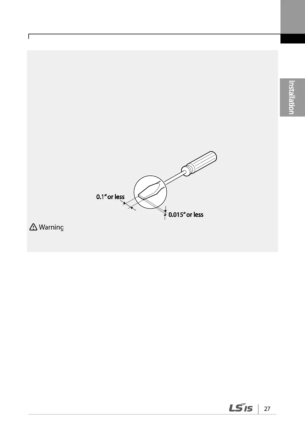
• When making control terminal cable connections, use a small flat-tip screw driver (0.1in wide
(2.5mm) and 0.015in thick (0.4mm) at the tip).
SA,SB, SC, they are shorted, have 24V voltage. Do not connect power to the inverter until installation
has been fully completed and the inverter is ready to be operated. Doing so may result in electric shock.
Step 5 PNP/NPN Mode Selection
The S100 inverter supports both PNP (Source) and NPN (Sink) modes for sequence inputs at the
terminal. Select an appropriate mode to suit requirements using the PNP/NPN selection switch
(SW1) on the control board. Refer to the following information for detailed applications.
PNP Mode (Source)
Select PNP using the PNP/NPN selection switch (SW1). Note that the factory default setting is NPN
mode. CM is is the common ground terminal for all analog inputs at the terminal, and P24 is 24V
internal source. If you are using an external 24V source, build a circuit that connects the external
source (-) and the CM terminal.