Rotational Directions for Different Voltage Inputs
Command / Voltage
Input
0
–
10 V -10
–
0 V
-10–10 V Voltage Input Setting Details
IN-12 V1- volt x1–
IN-15 V1- Perc y2
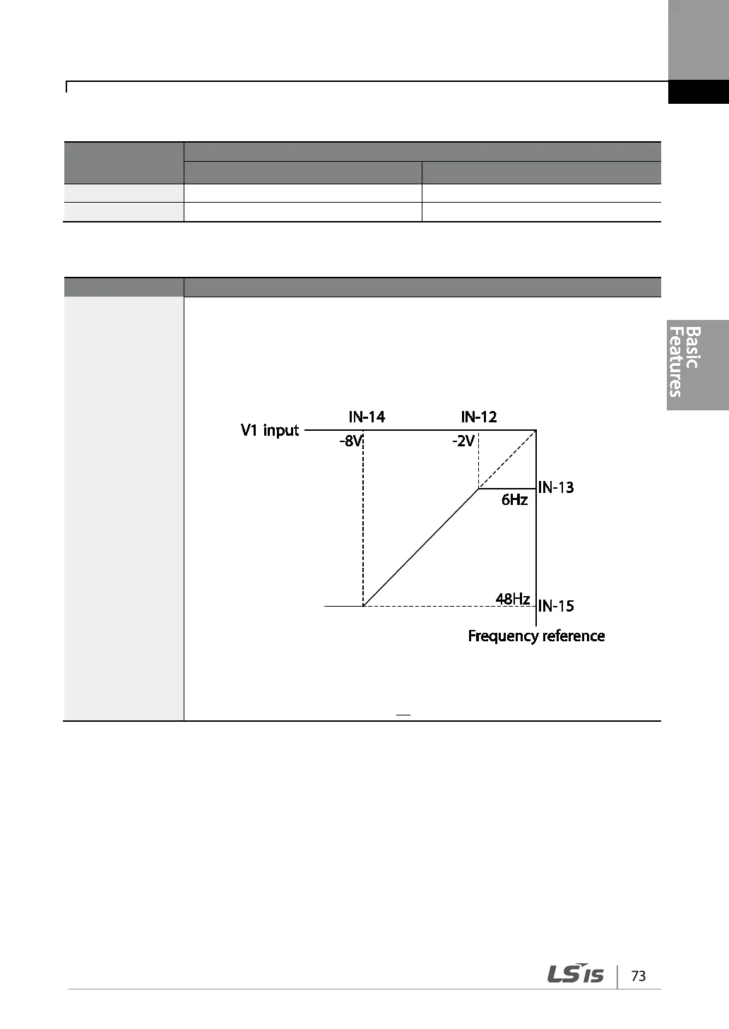
Sets the gradient level and off-set value of the output frequency in relation to the
input voltage. These codes are displayed only when IN-06 is set to 1 (bipolar).
As an example, if the minimum input voltage (at V1) is set to -2 (V) with 10%
output ratio, and the maximum voltage is set to -8 (V) with 80% output ratio
respectively, the output frequency will vary within the range of 6 - 48 Hz.
[IN-12 V1-volt X1–IN-15 V1 Perc y]
For details about the 0–+10 V analog inputs, refer to the code descriptions IN-08
V1 volt x1–IN-11 V1 Perc y2 on page 69.