1- 9
(2) Allocation of external input signal
Signal name
Operation content Reference
Axis
XBC-DN(P)
□□
S(U)/H
XEC-DN(P)
□□
H
limit
(LimitL)
X axis P0008 %IX0.0.8
Detected
at the falling edge of input
contact point
Normally
closed
contact point
point)
Y axis P000A %IX0.0.10
Detected at the falling edge of input
contact point.
External upper
limit
(LimitH)
X axis P0009 %IX0.0.9
Detected at the falling edge of input
contact point
Y axis P000B %IX0.0.11
Detected at the falling edge of input
contact point
DOG signal
X axis P000C %IX0.0.12 When homing, detected at rising edge
Normally
opened
contact point
point)
Y axis P000E %IX0.0.14 When homing, detected at rising edge
ORIGIN signal
X axis P000D %IX0.0.13 When homing, detected at rising edge
Y axis P000F %IX0.0.15 When homing, detected at rising edge
Input common
X/Y
axis
COM Input common terminal
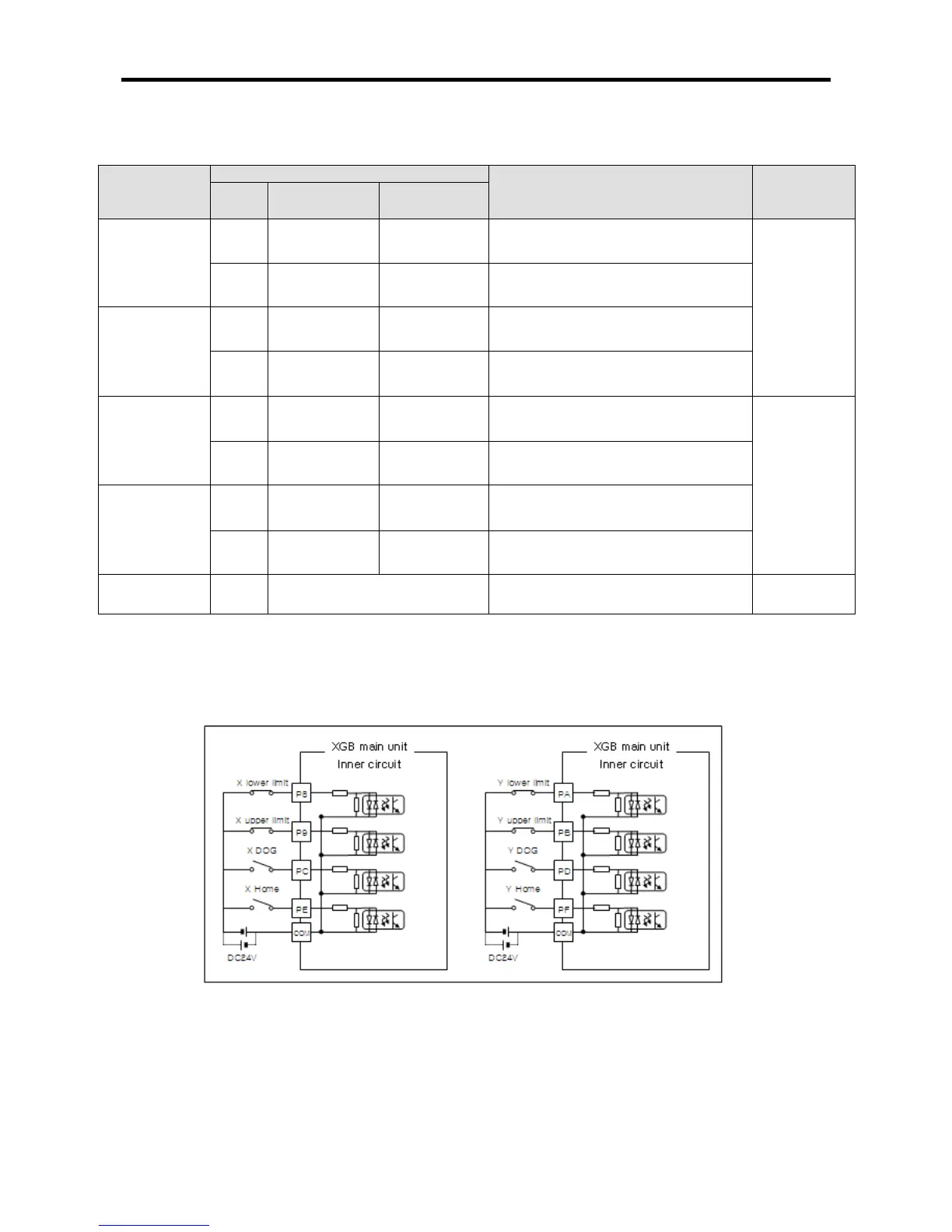
(3) Wiring example of external input signal
In case of using positioning function of XGB compact main unit, wiring example of input signal is as
follows.
(XBC-DN□□S(U)/H is used for example)
< XGB high-end positioning input signal wiring example >