Chapter 3 Before positioning
3- 53
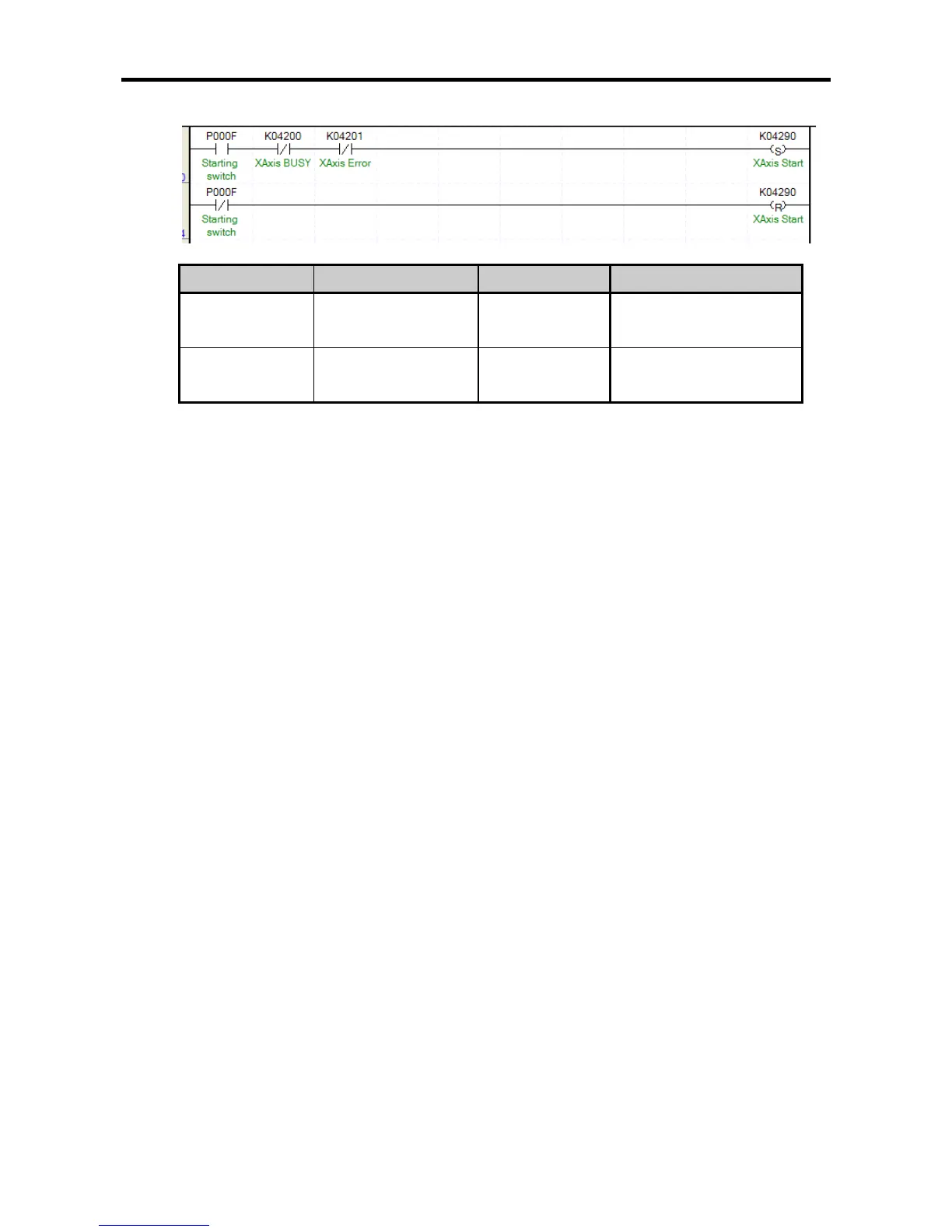
the external input starting switch (P000F) turns On.
Device Description Device Description
P000F(%IX0.0.15)
Axis X starting external
switch
K4201(%KX6721) Axis X error
K4200(%KX6720)
Axis X signal during
operation
K4290(%KX6864)
Axis X starting instruction
flag
• The program above is an example of the program that indirectly starts with the operation data of
the current step number (K426 word) on axis X by setting the starting signal whenever the
external input starting switch (P000F) turns On.
• When the starting switch turns On, the starting commanding flag (K4290) is set and axis X starts,
and when the starting switch turns Off, the starting contact point is reset.
• Note that the set coil is used for axis X starting commanding flag (K4290) instead of ordinary coil
output.
For example, if a toggle switch is used for the starting switch, and if the starting commanding flag
(K4290) is not set but ordinary coil output is used, there might be the problem that it is
automatically restarted by the bit Off during operation when positioning is completed. To avoid this,
use a push button switch for the external input switch, and use a set coil and reset coil according
to the On/Off of the input switch for the starting commanding flag.