215651 184 Revision B
$
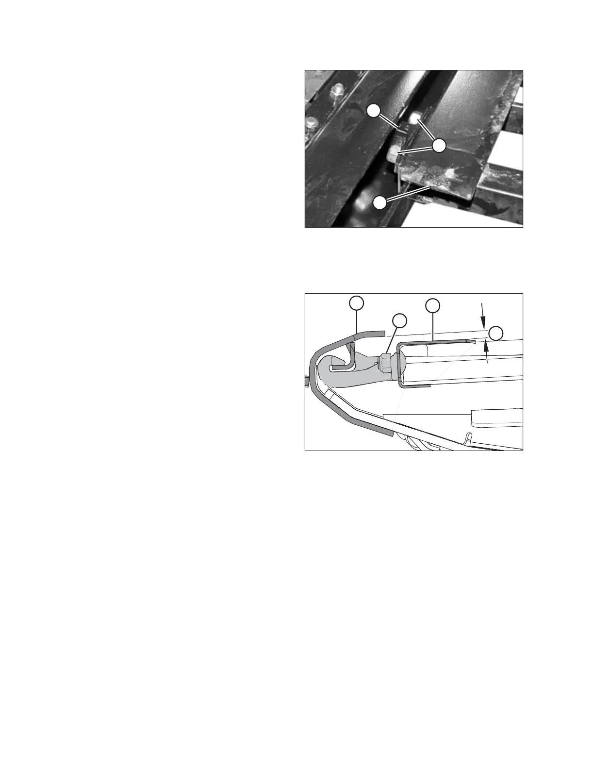
%
&
Figure 5.127: Deck Support
12. Loosen two lock nuts (A) on deck support (B) by one
half-turn ONLY .
NOTE:
The deck is shown with the draper removed. The number of
deck supports depends on the width of the header:
• D115X and D120X: Four supports
• D125X: Six supports
• D130XL: Six supports
• D135XL and D140XL: Eight supports
• D145XL: Ten supports
13. Tap deck (C) with a hammer to lower the deck relative to
the deck supports. Tap deck support (B) using a hammer
and punch to raise the deck relative to the deck supports.
14. Measure the thickness of the draper belt.
$
&
'
%
Figure 5.128: Deck Support
15. Locate a feeler gauge of the same thickness as the draper
belt plus 1 mm (0.04 in.).
16. Slide the feeler gauge along deck (A) under the cutterbar in
order to properly set the gap.
17. To create a seal, adjust deck (A) so that clearance (B)
between cutterbar (C) and the deck is the same thickness
as the draper belt plus 1 mm (0.04 in.).
NOTE:
When checking the clearance at either roller, measure the
gap beginning at the roller tube, NOT the deck.
18. Tighten deck support hardware (D).
19. Recheck gap (B) with the feeler gauge. For instructions,
refer to Step 15, page 184.
20. Repeat Steps 12, page 184 to 19, page 184 for each draper
deck support requiring adjustment.
21. Tension the draper. For instructions, refer to 5.7.3 Checking
and Adjusting Draper Tension, page 177.
MAINTENANCE AND SERVICING
 Loading...


