214366 49 Revision A
1005190
A
B
C
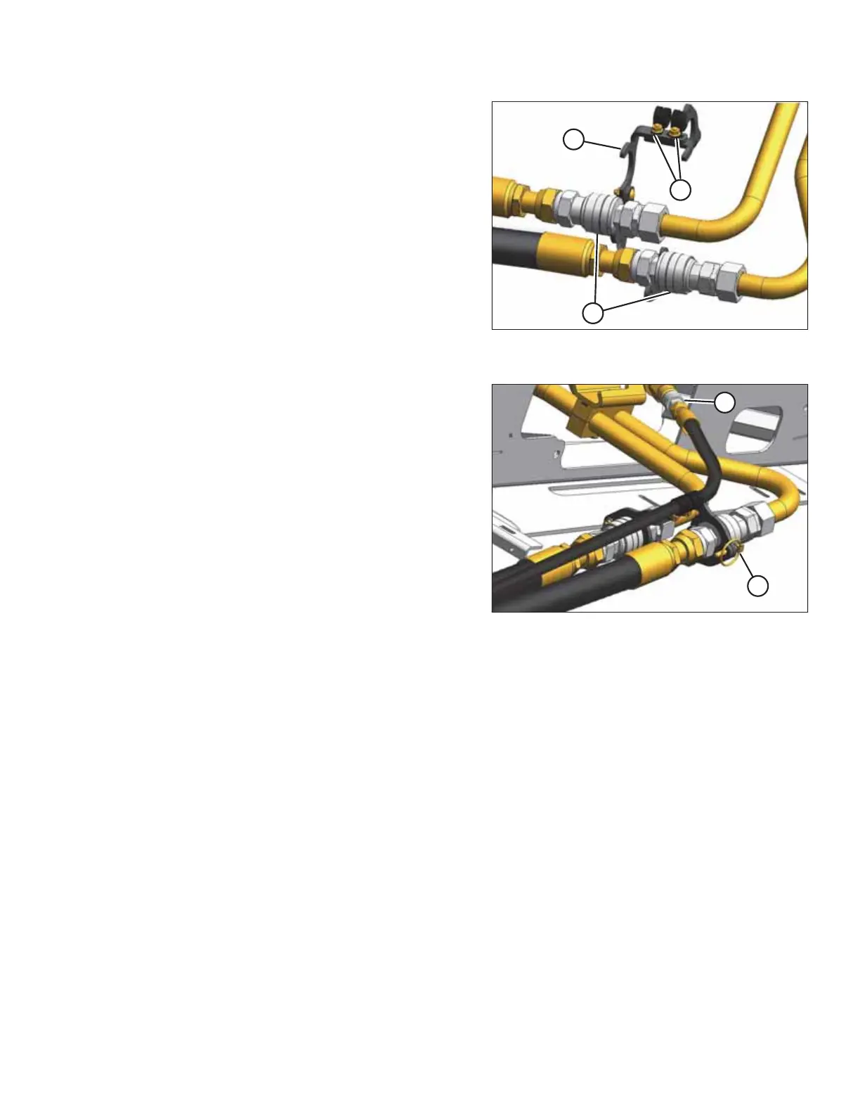
Figure 3.39: Hydraulic Couplers with
Coupler Lock
5. Lower holder (A) onto sleeves (B) so that the flats are
positioned on the holder.
NOTE:
Holder can be adjusted by loosening bolts (C). Tighten
bolts after adjusting.
1005191
A
B
Figure 3.40: Hydraulic Couplers with Case
Drain Hose
6. Insert lynch pin (A) to secure the lock.
7. Attach case drain hose coupler at (B).
8. Proceed to Step 5, page 50 and Step 6, page 51.
OPERATION