– Programming Manual 14. I/O test 97
Type of I/O port
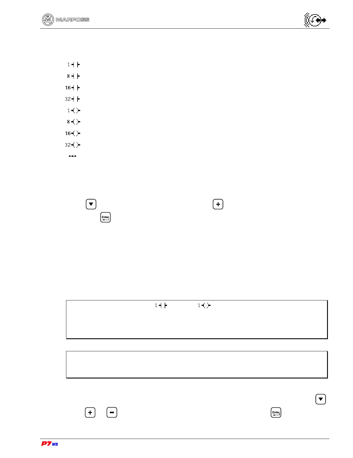
The meaning of the icons used is the following:
1 input bit
(byte) 8 input bits
(word) 16 input bits
(double word) 32 input bits
1 output bit
(byte) 8 output bits
(word) 16 output bits
(double word) 32 output bits
no I/O port has been selected.
With the color display, the input ports are represented in green and the output ports in
red.
To select the port (input, output, bit, byte, word or dword) to be viewed or changed,
press to highlight the desired field, press to view the desired type of port,
then press to confirm.
Number of I/O port
The range of the logical bits to be viewed is selected with the I/O port number based
on the type of I/O port (byte, word, dword) selected.
The maximum value of port number is controlled by the system based on the type of
port selected and the number of I/O ports.
Note: If an individual bit ( input or output) is selected as port type, the
value of the “I/O port number” field corresponds to the number of the
individual logical bit.
If 8, 16, 32 bits are selected, the port number indicates the byte.
Note: The correspondence between logical bit number and No. of pins of the I/O
connector(s) is reported on the “I/O list” relevant to the application in use,
present in the corresponding “Installation Manual”.
To select the number of port to be viewed, highlight the desired field by pressing ,
press
or until the desired number is displayed, then press to confirm.