46 10. Unit Set-up – Programming Manual
10.2.2.
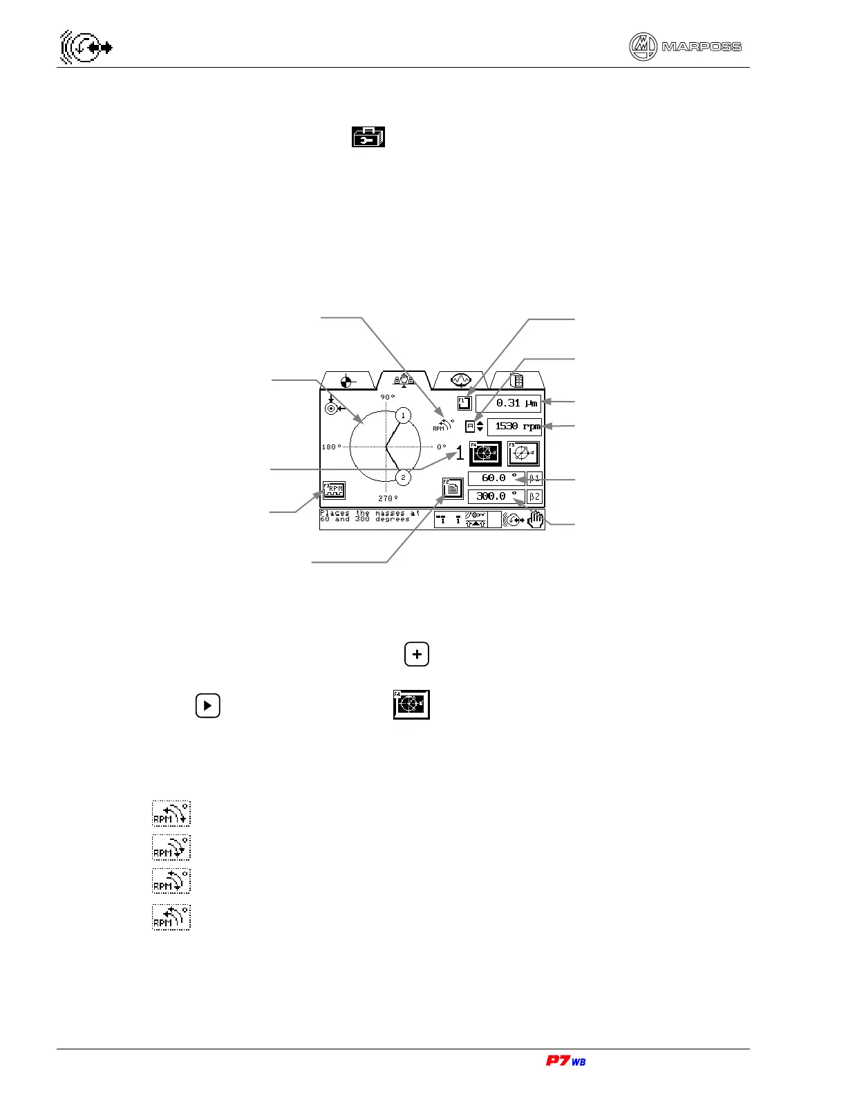
Manual balancing procedure with fixed weights/variable angles
Page B7 of the “Utilities” folder menu map (section 8.1, page 3).
Wheel balancing through angular positioning of two weights with pre-defined value
on the wheel flange.
Through a guided menu P7 supplies the angular values where the weights are to be
positioned in order to compensate the wheel unbalance.
(1) Measurement selection: present only in the applications with two logical channels.
With the field highlighted, press to select the desired measurement (the
number of the corresponding physical channel is displayed).
Press to highlight the F4 key .
(2) Wheel rotation direction (RPM) / Indexed scale direction (°). See section 18.1.1
“Wheel rotation direction (RPM) / Angle evaluation direction (°)“, page 3.
Wheel rotation → counter-clockwise / Indexed scale → clockwise
Wheel rotation → clockwise / Indexed scale → clockwise
Wheel rotation → clockwise / Indexed scale → counter-clockwise
Wheel rotation → counter-clockwise / Indexed scale → counter-clockwise
(3) The vibration value can be displayed either as width (unit of measure "micron" or
"inch") or speed (unit of measure "mm/sec" or "inch/sec"). The display mode is
defined when configuring the application.
Graphic representation of
weights angular position
Angular position of
weight 1
Measurement selection (1)
Wheel rotation speed
Procedure repetition
Vibration value (3)
Wheel rotation direction /
Indexed scale direction (2)
Angular position of
weight 2
Viewing of procedure
summary page
No. of physical channel
RPM sensor control