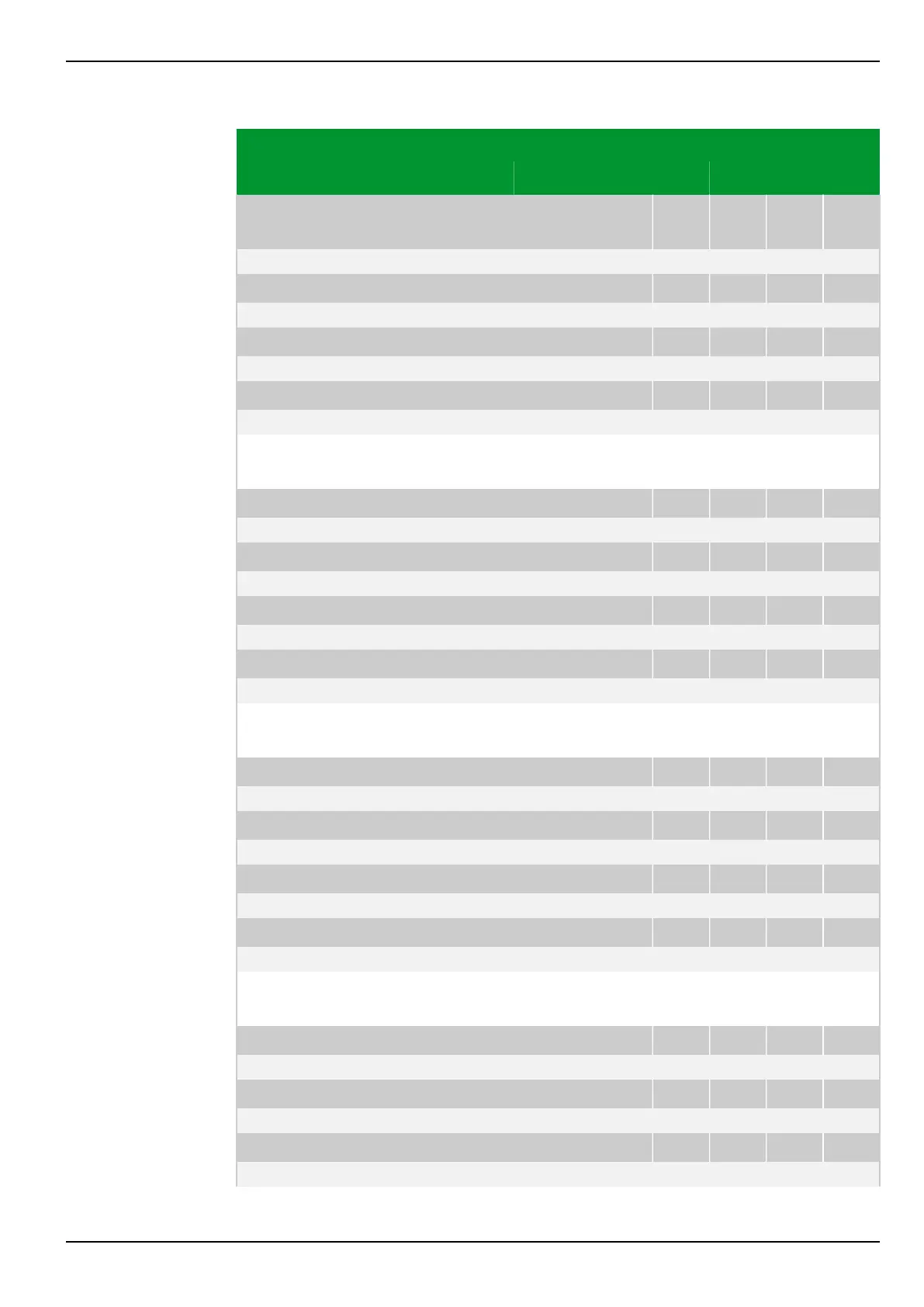
Parameter Address
Default Min Max Unit Logic Diagram
Definite-time over‐
current protection
DTOC1: Enable PSx
076 050 077 050 078 050 079 050
0: No Fig. 3-107, (p. 3-153)
[spacer]
DTOC2: Enable PSx
076 070 077 070 078 070 079 070
0: No
[spacer]
DTOC3: Enable PSx
076 180 077 180 078 180 079 180
0: No
[spacer]
DTOC4: Enable PSx
099 060 099 061 099 062 099 063
0: No
[spacer]
This setting specifies the parameter subset to be enabled for definite-time
overcurrent protection.
[spacer]
DTOC1: Block tim.st. IN PSx
076 067 077 067 078 067 079 067
0: Without Fig. 3-111, (p. 3-158)
[spacer]
DTOC2: Block tim.st. IN PSx
076 087 077 087 078 087 079 087
0: Without
[spacer]
DTOC3: Block tim.st. IN PSx
076 108 077 108 078 108 079 108
0: Without
[spacer]
DTOC4: Block tim.st. IN PSx
099 124 099 125 099 126 099 127
0: Without
[spacer]
This setting defines whether blocking of the residual current stages will take
place for single-pole or multi-pole phase current starting.
[spacer]
DTOC1: Gen.starting modePSx
076 066 077 066 078 066 079 066
1: With start. IN/Ineg Fig. 3-112, (p. 3-159)
[spacer]
DTOC2: Gen.starting modePSx
076 086 077 086 078 086 079 086
1: With start. IN/Ineg
[spacer]
DTOC3: Gen.starting modePSx
076 106 077 106 078 106 079 106
1: With start. IN/Ineg
[spacer]
DTOC4: Gen.starting modePSx
099 120 099 121 099 122 099 123
1: With start. IN/Ineg
[spacer]
This setting defines whether starting of the residual current stages will result in
the formation of the general starting signal of DTOC protection.
[spacer]
DTOC1: tGS PSx
076 065 077 065 078 065 079 065
0.00 0.00 100.00 s Fig. 3-112, (p. 3-159)
[spacer]
DTOC2: tGS PSx
076 085 077 085 078 085 079 085
0.00 0.00 100.00 s
[spacer]
DTOC3: tGS PSx
076 107 077 107 078 107 079 107
0.00 0.00 100.00 s
7 Settings P634
P634/EN M/R-42-A // P634‑311‑653 7-157
 Loading...
