EasyManua.ls Logo

Mitsubishi MELSEC Q Series User Manual

Mitsubishi MELSEC Q Series
664 pages
To Next Page IconTo Next Page
To Previous Page IconTo Previous Page
Page #437 background imageLoading...
Page #437 background image
10
FUNCTIONS AND PROGRAMMING
10.3 Programming Using MELSEC Data Link Functions
10.3.1 MELSEC data link function list
10 - 36
9
UTILITY OPERATION
10
FUNCTIONS AND
PROGRAMMING
11
OVERVIEW OF
MULTIPLE CPU
SYSTEM
12
MULTIPLE CPU
SYSTEM
CONFIGURATION
13
MULTIPLE CPU
SYSTEM
CONCEPT
14
COMMUNICATIONS
BETWEEN CPU
MODULES
15
PARAMETERS
ADDED FOR
MULTIPLE CPU
16
PRECAUTIONS FOR
USE OF AnS SERIES
MODULE
10.3 Programming Using MELSEC Data Link Functions
This section explains the MELSEC data link functions contained in SW PVC-CCPU.
10.3.1 MELSEC data link function list
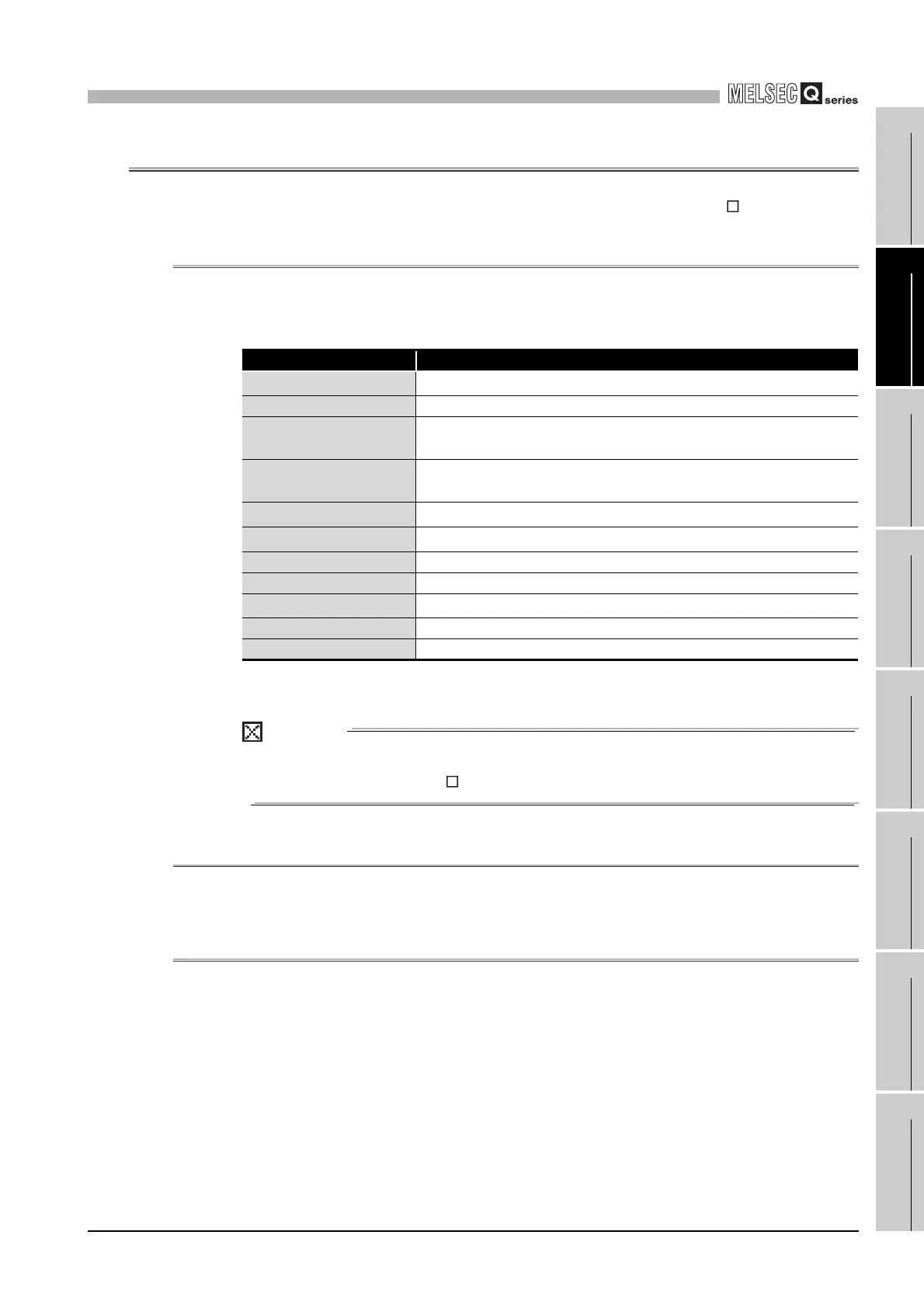
The following lists the MELSEC data link functions.
* 1 If an address indicated by an argument pointer is illegal, the return value of the function is a
pointer address specification error (-28628).
POINT
For details of the MELSEC data link functions, refer to the MELSEC data link
function HELP of SW PVC-CCPU.
10.3.2 Programming procedure
Refer to Section 10.2.2 for details of the programming procedures.
10.3.3 Creating new project of user program and compiling method
Refer to Section 10.2.3 for details of new project creation and compiling method.
Table10.11 MELSEC data link function list
Function name Description
mdOpen
*1
Open a communication line.
mdClose Close a communication line.
mdSend
*1
Perform batch write of devices.
Send message data (SEND function)
mdReceive
*1
Perform batch read of devices.
Receive message data (RECV function)
mdRandW
*1
Write devices randomly.
mdRandR
*1
Read devices randomly.
mdDevSet Set bit device.
mdDevRst Reset a bit device.
mdTypeRead
*1
Read the type of programmable controller CPU.
mdControl Remote RUN/STOP/PAUSE
mdInit Refresh the programmable controller device address table.

Table of Contents

Other manuals for Mitsubishi MELSEC Q Series

Questions and Answers:

Mitsubishi MELSEC Q Series Specifications

General IconGeneral
SeriesMELSEC Q Series
TypeModular PLC
Programming SoftwareGX Works2, GX Works3
CategoryProgrammable Logic Controller (PLC)
I/O ModulesDigital I/O, Analog I/O, High-Speed Counter, Positioning
CommunicationEthernet, CC-Link
Programming LanguagesLadder Logic, Structured Text, Function Block Diagram, Sequential Function Chart, Instruction List
MemoryFlash Memory
I/O PointsUp to 4096 points (expandable with additional modules)
Power SupplyAC or DC power supply options available, depending on the base unit and modules.
MountingDIN rail mounting
Operating Temperature0°C to 55°C
Storage Temperature-25°C to 75°C
Humidity5% to 95% (non-condensing)
Vibration Resistance10 to 57 Hz, 0.075mm amplitude
WeightVaries depending on the module, from a few grams to several kilograms.
Shock Resistance147 m/s² (3 times each in X, Y, Z directions)

Summary

CHAPTER1 OVERVIEW

1.1 Features

Describes the features of the C Controller module, including VxWorks, standard ROM, large data storage, and I/O control capabilities.

CHAPTER2 SYSTEM CONFIGURATION

2.1 System Configuration

Explains device configuration, development environment connection, and system configuration overview for C Controller systems.

2.1.1 Devices to be used

Details the base units, extension cables, power supply modules, and other components used with the C Controller module.

CHAPTER3 SPECIFICATIONS

3.1 General Specifications

Provides the general specifications of the C Controller module, including operating ambient temperature, humidity, vibration, and shock resistance.

CHAPTER4 FUNCTIONS

4.1 Function List

Lists the functions of the C Controller module, such as I/O module access, remote operation, and self-diagnostic functions.

CHAPTER5 SETTINGS AND PROCEDURES BEFORE OPERATION

5.1 Handling Precautions

Explains critical handling precautions for the C Controller module, including environment, installation, and connection safety.

CHAPTER6 I/O NUMBER ASSIGNMENT

6.1 Relation between No. of Base Units and No. of Slots

Explains how base units and slots relate to I/O number assignment for the C Controller module.

CHAPTER7 MEMORIES AND FILES HANDLED BY C CONTROLLER MODULE

7.1 Memory of C Controller Module

Explains user memories (Standard ROM, Work RAM, Battery-backed-up RAM, CompactFlash) and system memory.

CHAPTER8 INSTALLING AND UNINSTALLING SW[]PVC-CCPU

8.1 Development Environment

Details the product requirements for the development environment, including personal computer specifications and operating system.

CHAPTER9 UTILITY OPERATION

9.1 Common Utility Operations

Explains common operations for utilities, including starting, exiting, setting connection targets, and displaying help screens.

CHAPTER10 FUNCTIONS AND PROGRAMMING

10.1 Outline of Functions

Outlines bus interface functions and MELSEC data link functions supplied with SW PVC-CCPU for accessing modules and CPUs.

CHAPTER11 OVERVIEW OF MULTIPLE CPU SYSTEM

11.1 What is Multiple CPU System ?

Defines the multiple CPU system concept, explaining how multiple CPU modules work together for enhanced performance.

CHAPTER12 MULTIPLE CPU SYSTEM CONFIGURATION

12.1 System Configuration

Explains system configuration for multiple CPU systems, including device compatibility and connection methods.

CHAPTER13 MULTIPLE CPU SYSTEM CONCEPT

13.1 Mounting Position of CPU Module

Details the mounting positions of CPU modules (C Controller, Basic QCPU, High Performance QCPU, Motion CPU) in a multiple CPU system.

CHAPTER14 COMMUNICATIONS BETWEEN CPU MODULES

14.1 Data Communications by MELSEC Data Link Functions

Explains data communication methods using MELSEC data link functions between CPU modules, including auto refresh and shared memory.

CHAPTER15 PARAMETERS ADDED FOR MULTIPLE CPU SYSTEM

15.1 Parameter List

Lists parameters required for multiple CPU system operation, highlighting setup necessity and consistency checks in the C Controller setting utility.

CHAPTER16 PRECAUTIONS FOR USE OF AnS SERIES MODULE

16.1 Precautions for Use of AnS Series Module

Provides specific precautions for using AnS series modules, including applicable I/O and special function modules and control CPU settings.

CHAPTER18 TROUBLESHOOTING

18.1 Troubleshooting Basics

Provides fundamental steps for troubleshooting, including visual checks, fault verification, and narrowing down the error cause.

Related product manuals