14
COMMUNICATIONS BETWEEN CPU MODULES
14.3 Data Communications Using CPU Shared Memory
14.3.1 CPU shared memory structure
14 - 12
9
UTILITY OPERATION
10
FUNCTIONS AND
PROGRAMMING
11
OVERVIEW OF
MULTIPLE CPU
SYSTEM
12
MULTIPLE CPU
SYSTEM
CONFIGURATION
13
MULTIPLE CPU
SYSTEM
CONCEPT
14
COMMUNICATIONS
BETWEEN CPU
MODULES
15
PARAMETERS
ADDED FOR
MULTIPLE CPU
16
PRECAUTIONS FOR
USE OF AnS SERIES
MODULE
* 2 Stores 0 when no error is detected.
Table14.11 List of host CPU operation information areas
CPU shared
memory
address
Name Description Details
0H Information presence Information flag
The area for checking if information is stored in the host CPU's
operation information area (1H to 1FH,) or not.
0: No information, 1: Information exists
1H Diagnostic error Diagnostic error number
An error No. identified at occurrence of an error during diagnostics
is stored in BIN.
*2
2H
Date and time of
diagnostic error
Date and time of
diagnostic error
The year and month when the error number was stored in the CPU
shared memory's 1
H
address, are stored with two digits of the BCD
code.
*2
3H
The day and time when the error number was stored in the CPU
shared memory's 1
H
address, are stored with two digits of the BCD
code.
*2
4H
The minutes and seconds when the error number was stored in the
CPU shared memory's 1
H
address, are stored with two digits of the
BCD code.
*2
5H
Error information
identification code
Error information
identification code
Stores an identification code to determine what error information
has been stored in the common error information and individual
error information.
*2
6H to 10H
Common error
information
Common error
information
The common information corresponding to the error number
identified during diagnostic is stored.
*2
11H to 1BH
Individual error
information
Individual error
information
The individual information corresponding to the error number
identified during diagnostic is stored.
*2
1CH Empty Cannot be used
1DH Switch status
C Controller module
switch status
Stores the C Controller module switch status.
0: RUN, 1: STOP
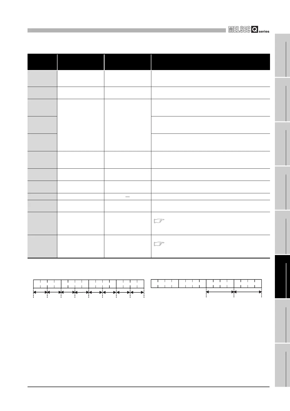
1EH LED status
C Controller module LED
status
Stores the C Controller module's LED bit pattern.
(
Figure 14.8)
The same data can be obtained by the QBF_ReadStatusEx
function.
1FH
C Controller module
operation status
C Controller module
operation status
Stores the C Controller module's operation status.
(
Figure 14.9)
The same data can be obtained by the QBF_ReadStatusEx
function.
Figure 14.8 LED status Figure 14.9 Operation status
B0
B3B4B7B8B11B12B15
4)
5)
3) 2) 1)
1):
RUN
2): ERR.
3): USER
4): CF CARD
7)
8)
6)
5): Reserved
6): Reserved
7): Reserved
8): MODE
<LED status>
1) to 4)
0: Off
1: On
2: Flickering (slow)
3: Flickering (fast)
8)
0: Off
1: Lit green
2: Reserved
3: Flickering green
B0
B3B4B7B8B11B12B15
2) 1)
1): C Controller module operation status
2): STOP/PAUSE factor
(in chronological order)
0: RUN
1: Reserved
2: STOP
3: PAUSE
0: RUN/STOP/MODE switch
1: Reserved
2: Remote operation from
C Controller setting utility
3: Execution of QBF_Control
function from user program
4: Error