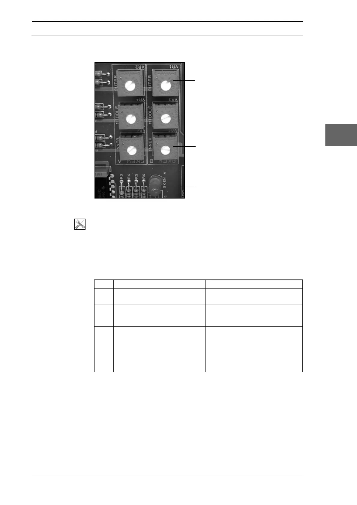
Outer Sensor-Pair
Middle Sensor-Pair
Inner Sensor-Pair
LED1 - Bank A
Bank A
Bank B
Morgana DocuMaster MFC - Service Manual 93
4. Service Procedures - Machine Adjustments and Calibration
Figure 4.72 The Edge-Sensor Set Adjustment Potentiometers
Tools:
• Screwdriver: Small Flat-Blade
• Test Stri p (See Section 4.1.3).
Before you start:
• Remove the electrical cabinet cover (See Section 4.2.12)
• Clean the edge-sensor set (See Section 4.13.4).
Step Action Information
1 Set the main input switch to the ON
(I) position.
Make sure that the emergency stop
button is not pushed in.
2 Set a sheet width value of less
than
208mm on the GUI panel.
(See the DocuMaster MFC User
Operating Instructions) or use the
MFC Test program.
3 Do a check that th
e inner sensor-
pair is set to be on.
• Put test strips over the inner
sensor-pair.
• Make sure that LED1 and LED2
on the controller PCB come on
(see Figure 4.72).
• Remove the test strips.