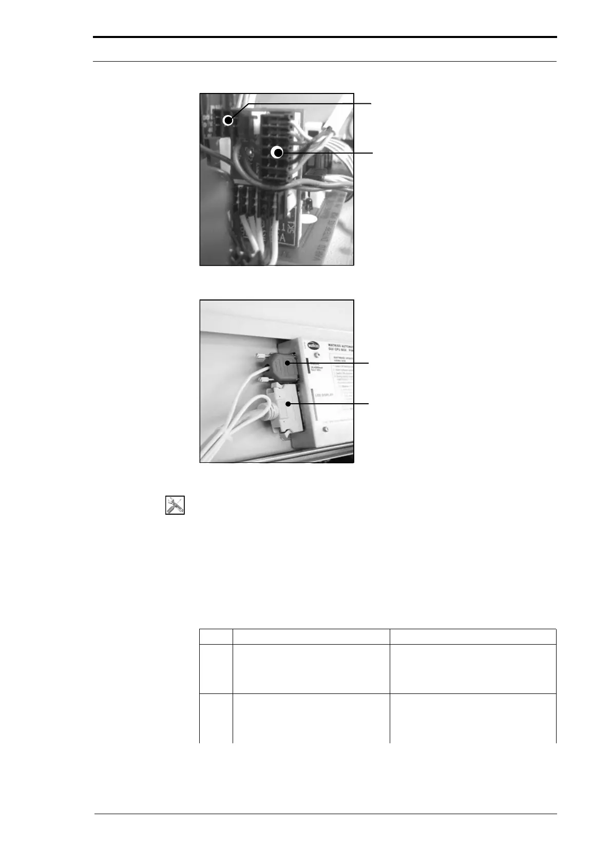
PL3 - Feed Signal Cable
PL2 - PWM Signal Cable
4. Service Procedures - Replace Components - DRV Module
108 Morgana DocuMaster MFC - Service Manual
Figure 4.89 Signal Interface PCB Connections
RS232 Serial Comms Connector
GUI Panel Interface Cable
Figure 4.90 CPU Serial Comms and GUI Connections
Tools:
• Allen Key: 3mm
• Spanner: 10mm, 14mm
• Pliers: Side Cutters.
Before you start:
• Remove the RH and LH side covers (See Section 4.2.5) and (See Section 4.2.6)
• Remove the rear guard (See Section 4.2.7)
• Remove the CAP (See Section 4.6.1).
Step Action Information
1 Disconnect the Power Bus and
Data bus cables from the interface
PCB. Pull the cables out through
the RH side plate.
(See Figure 4.87).
2 Disconnect the feed-signal cable
from PL3 on
the signal interface
PCB. Pull the cable out through the
RH side plate.
(See Figure 4.89)