Morgana DocuMaster MFC - Service Manual 109
4. Service Procedures - Replace Components - DRV Module
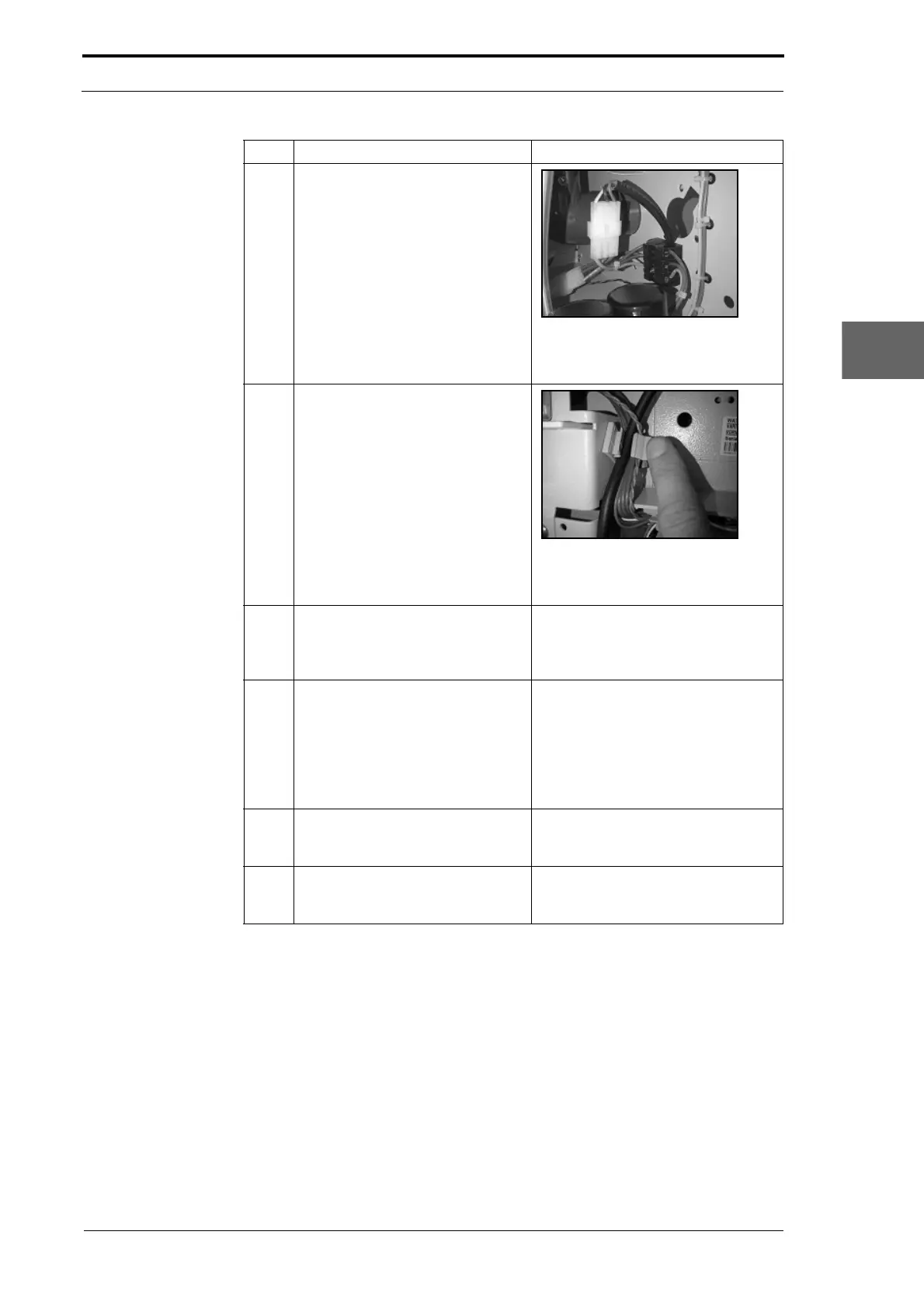
3 Disconnect the electrical cabinet
power supply cable at the
connection inside the DRV. Pull the
cable out through the RH side
plate.
Figure 4.91 Power Connection
The electrical cabinet power supply
cable connector inside the DRV.
4 Open the 3 cable clamps and
release the Power
Bus cable, Data
Bus cable, creaser power supply
cable and signal cable from the RH
side plate.
Figure 4.92 Cable Clamp
Press against the tab on the cable
clamp to open the cable clamp.
5 Disconnect the PWM cable from
PL2
on the signal interface PCB.
Pull the cable out through the LH
side plate.
(See Figure 4.89).
6 Disconnect the RS232 serial
comms cable
and the GUI
interface cable from the GUI CPU.
Pull the cables out through the LH
side plate.
The RS232 serial connector fixing
screws
are captured and remain with
the connector.
• Press both of the latches on the
GUI interface cable connector
and pull the connector away from
the CPU.
7 Disconnect the main drive motor
power cable from the creaser
module.
Put the cable inside the DRV.
8 Disconnect the ioniser bar cable
from the high
voltage anti-static
transformer.
(See Section 4.11.4).
Step Action Information