6. General Procedures - The MFC Machine Configuration Wizard Description
208 Morgana DocuMaster MFC - Service Manual
6.7.3 The Crease Position Information
The calibration setting field shows the electronic trim value that is currently set. You
can adjust this value to calibrate the creaser module. Here, the 'Skew Offset' trim is set
to zero (see Figure 6.12). This shows that no electronic trim has been set.
To set the trim value:
• Click inside the setting field.
• Type a new value - prefix with (+) or (-).
• Or, Click an arrow button to make a small adjustment.
Note: Y
ou do not need to press the ENTER key to store a trim
adjustment.
Caution: You must only adjust calibration trims if you do the ‘Calibrate the Crease
Module’ procedure (see Section 4.5.18). If you do not obey this instruction the crease
position will not be accurate.
6.7.4 The Command Buttons
The command buttons control navigation through the MCW.
Command Button Information
When you have completed a calibration procedure, Click
'Next' to move to the next calibration page.
If you need to return to a calibration page, Click 'Back' to
move to the previous calibration page.
If you need to exit the MCW, Click 'Cancel' to close the
MCW program.
Note: If you
'Cancel' the MCW program, any trim adjustments
you made will not be written to the EEROM.
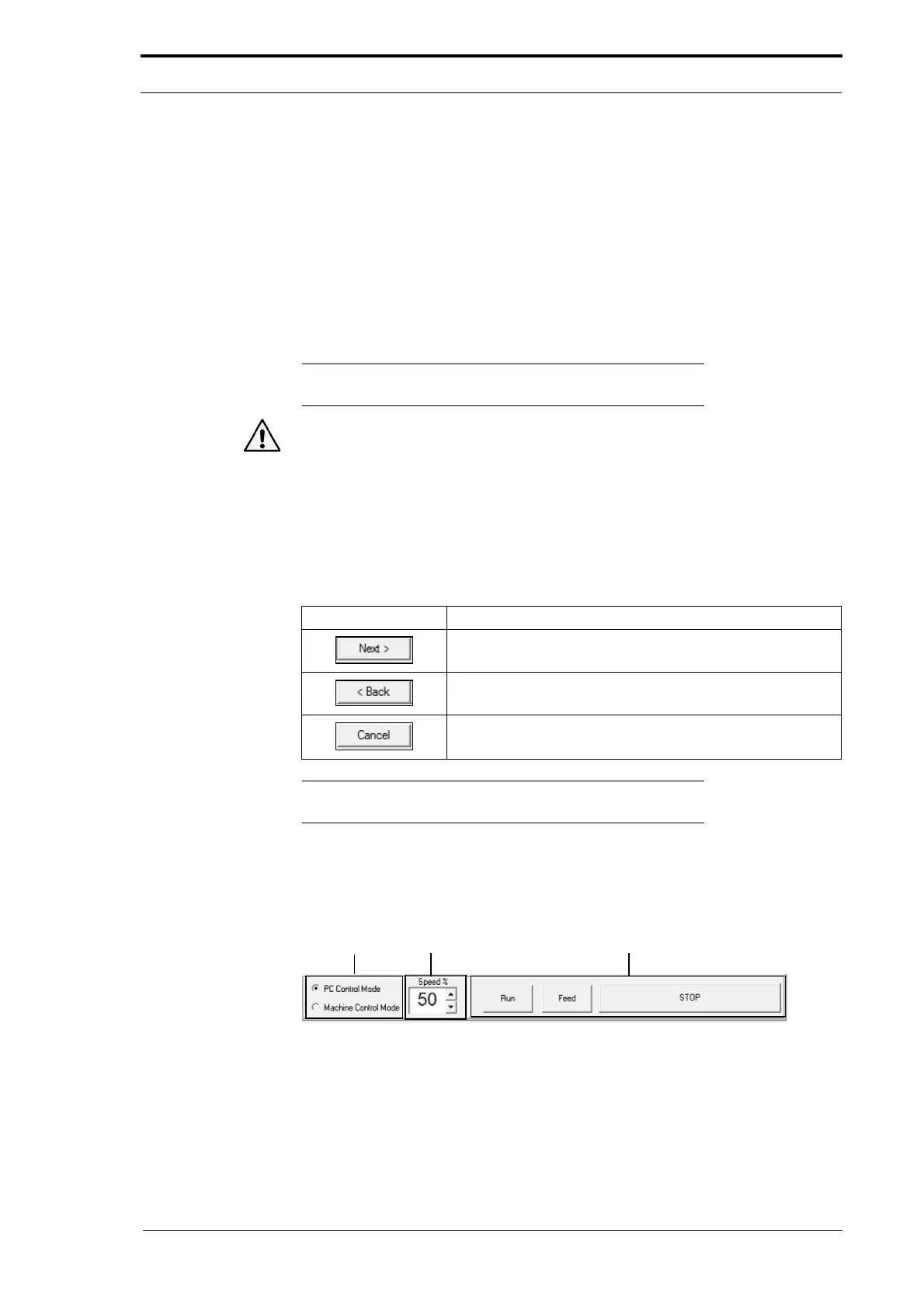
6.7.5 The Control Bar
Control Buttons
Motor Speed
Control
Control
Mode
Figure 6.13 The Parts Of The Control Bar
PC Control Mode
The primary function of PC Control Mode is to let a production test engineer test and
calibrate the creaser module when it is manufactured. It is not recommended that you
use PC Control Mode unless a service procedure tells you to.