Morgana DocuMaster MFC - Service Manual 215
7. Electrical and Control System - Low Voltage Transformer Tappings
7.2 Low Voltage Transformer Tappings
7.2.1 Low Voltage Transformer Input
A transformer in the DRV module energizes two low voltage AC circuits to the interface
PCB. The two AC circuits are rectified by the interface PCB to become low voltage DC
circuits that energize the MFC’s electronic and electrical systems.
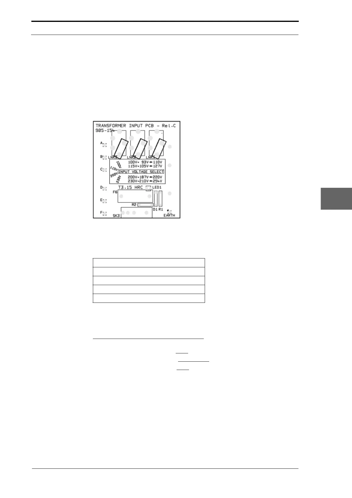
Figure 7.1 Low Voltage Transformer PCB and Taps
The transformer input PCB has four input voltage settings. The tappings must be set to
the nominal mains input voltage for a specific locality (see Section 4.5.3).
Tap Setting Input Voltage (VAC)
100V 93V – 100V
115V 105V – 127V
200V 187V – 220V
230V 210V – 254V
Example: the transforme
r taps are set to the 230V positions on a machine installed in
the UK.
228V Input = (210V – 254V range) = 230V Tap
• The measured input voltage = 228V
• The local input voltage range = 210V – 254V
• Use transformer tap position = 230V
If the local voltage is measured to be in the stated tap range the machine will function
correctly. When a local voltage is unstable and is frequently measured below the
nominal tap setting, the low voltage 28VDC output will decrease (this circuit is not
regulated). This can cause components connected to the unregulated 28VDC rail to
not operate correctly.
Example: The
vacuum valve solenoids do not open quickly, which causes feed
errors.The local input voltage is usually 210V – 254V, so the transformer taps are set to
the 230V position. After a voltage check is done the input voltage is measured to be
207V – 216V.