Morgana DocuMaster MFC - Service Manual 217
7. Electrical and Control System - PCBs
7.3 PCBs
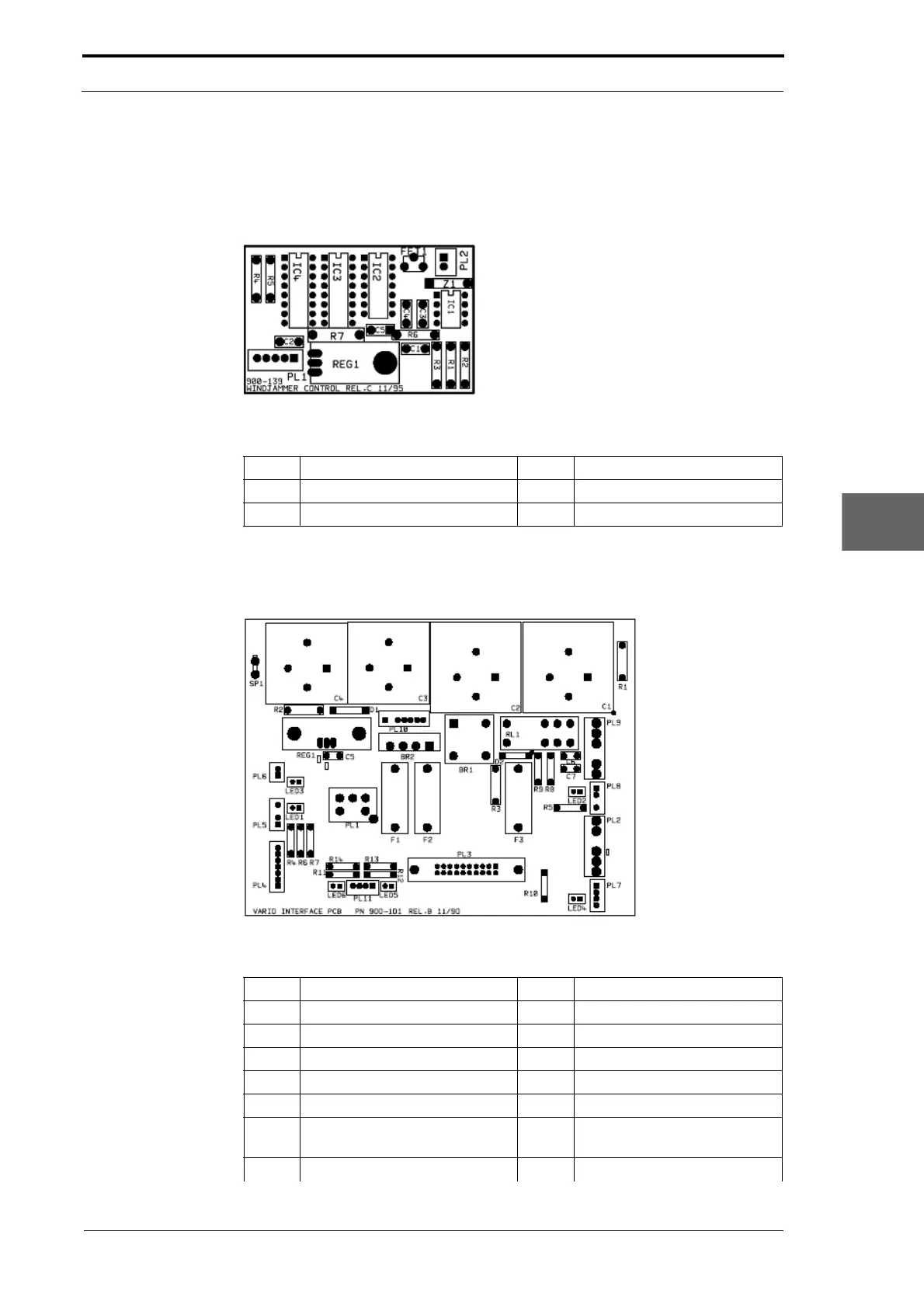
7.3.1 Windjammer Control PCB
Figure 7.2 Windjammer Control PCB
Description LED LED Function (LED ON)
PL1 Data input from GUI CPU
PL2 Data output to vacuum pump
7.3.2 Interface PCB
Figure 7.3 Interface PCB
Description LED LED Function (LED ON)
PL1 Input from transformer
PL2 Power bus to feed bins
PL3 Input from GUI CPU
PL4 Connection to motor drive PCB
PL5 Not used LED1 N/A
PL6 Vacuum control output LED3 Control signal to vacuum
pump
PL7 Data bus to feed bins LED4 Trigger signal to feed bins