7. Electrical and Control System - PCBs
218 Morgana DocuMaster MFC - Service Manual
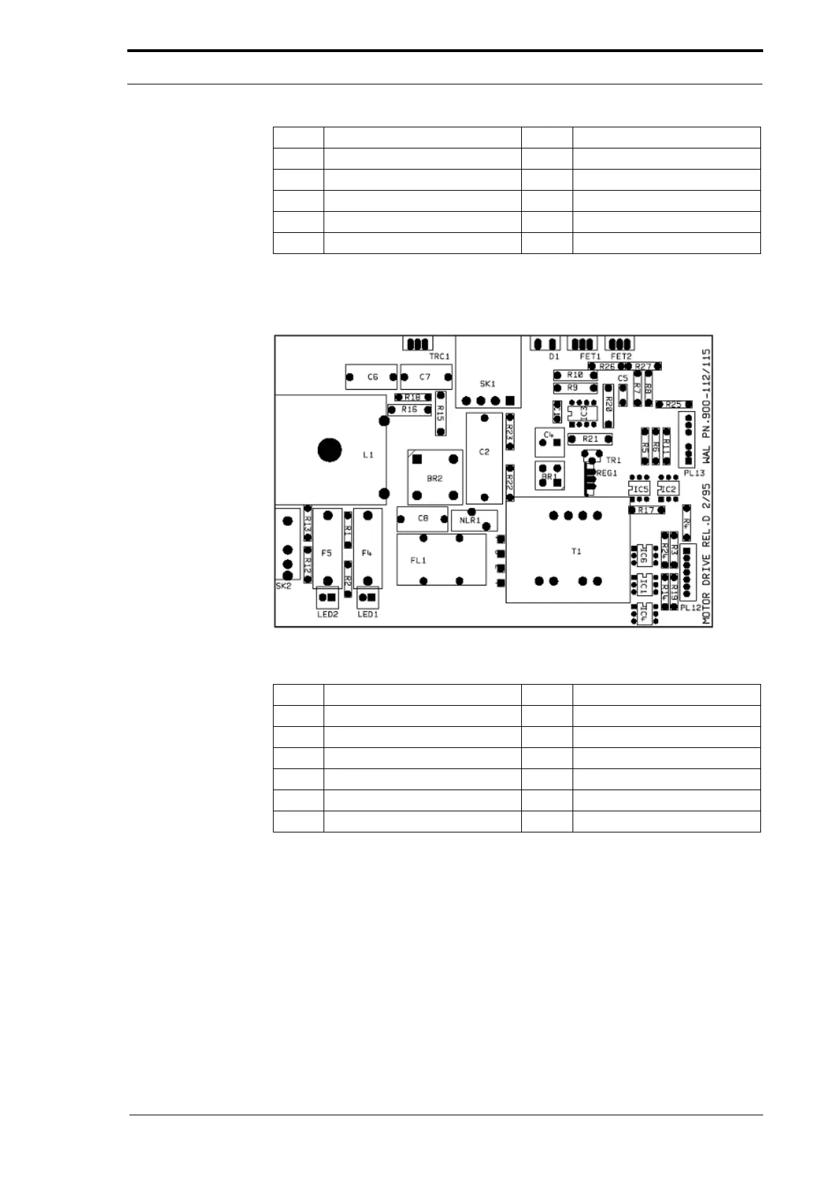
7.3.3 Motor Drive PCB
Figure 7.4 Main Motor Drive PCB
Description LED LED Function (LED ON)
PL12 Connection to interface PCB
PL13 Not used
SK1 Power to blower motor
SK2 Mains power input
F4 Fuse F4 LED1 F4 Fuse blown (when OFF)
F5 Fuse F5 LED2 F5 Fuse blown (when OFF)
PL8 Not used LED2 N/A
PL9 Not used
PL10 Zerox PCB
PL11 Rear guard switch LED5 Rear guard is closed
N/A Emergency stop switch LED6 E-stop switch not in
Description LED LED Function (LED ON)