Morgana DocuMaster MFC - Service Manual 219
7. Electrical and Control System - PCBs
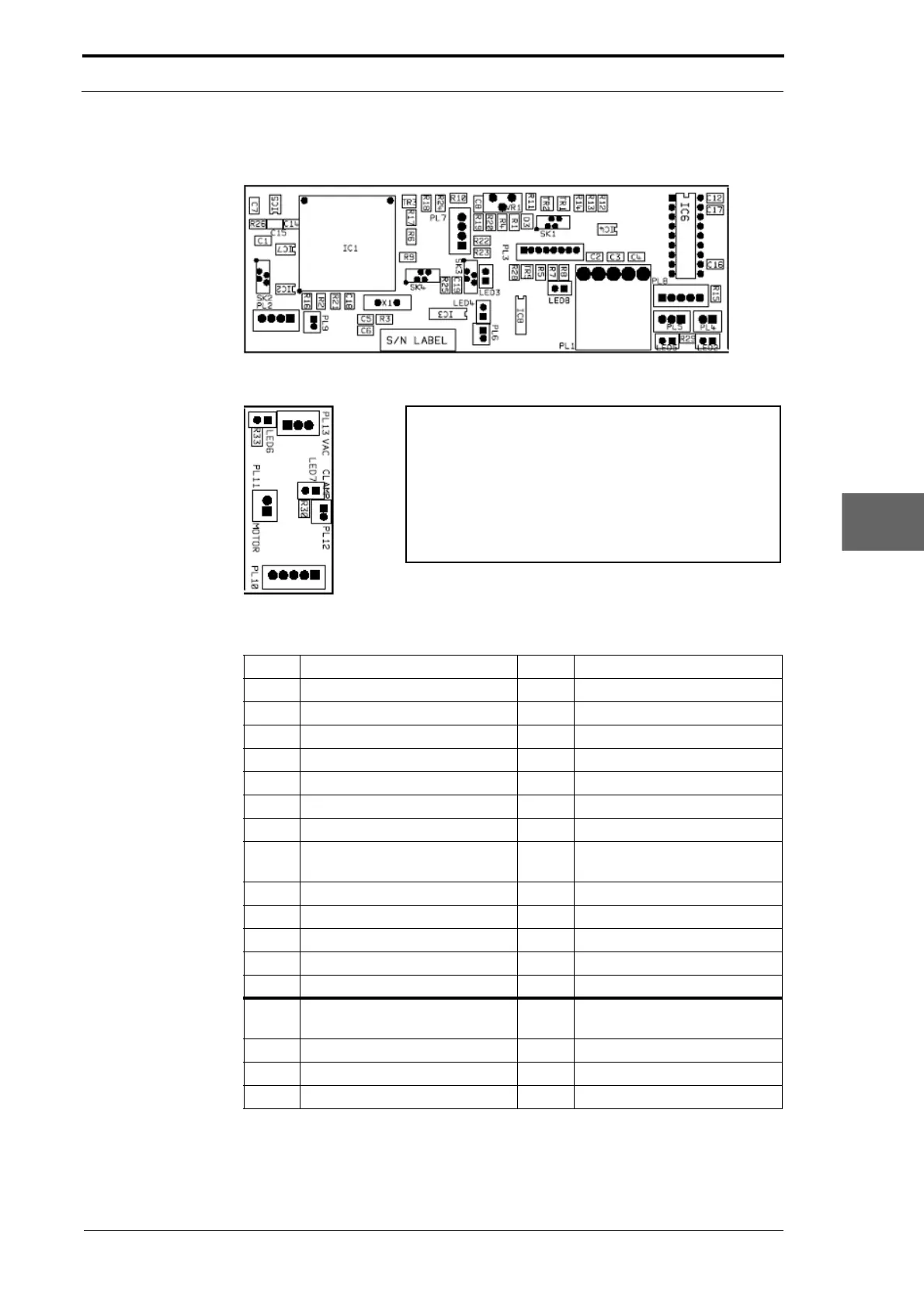
7.3.4 Suction Feed Bin Control PCB
Figure 7.5 Suction Feed Bin Control PCB
Note:
The Suction Feed Bin Control PCB is divided into two parts.
• The large Control PCB is attached to the RH side of the
feed bin.
• The small distributor PCB is attached to the chain
tensioner plate on the LH side of the feed bin.
Figure 7.6 Suction Feed Bin Control Distributor PCB
Description LED LED Function (LED ON)
PL1 Power bus input
PL2 Data bus I/O
PL3 Feed bin control switch
PL4 Feed clutch output LED2 Feed clutch signal output
PL5 Blow valve output LED5 Blow valve signal output
PL6 Not used
PL7 Not used
PL8 Connection to PL10 on LH side
of the
MFC
PL9 Not used
SK1 Emitter/sensor Check in Bin Test mode
SK2 Tray loaded sensor Shown on bin control switch
SK3 Tray down sensor LED3 Tray down
SK4 Tray height sensor LED8 Tray up
PL10 Connection to PL8 on the RH
side of the MFC
PL11 Tray lift motor output
PL12 Paper stop solenoid
PL13 Vacuum valve output