7. Electrical and Control System - PCBs
226 Morgana DocuMaster MFC - Service Manual
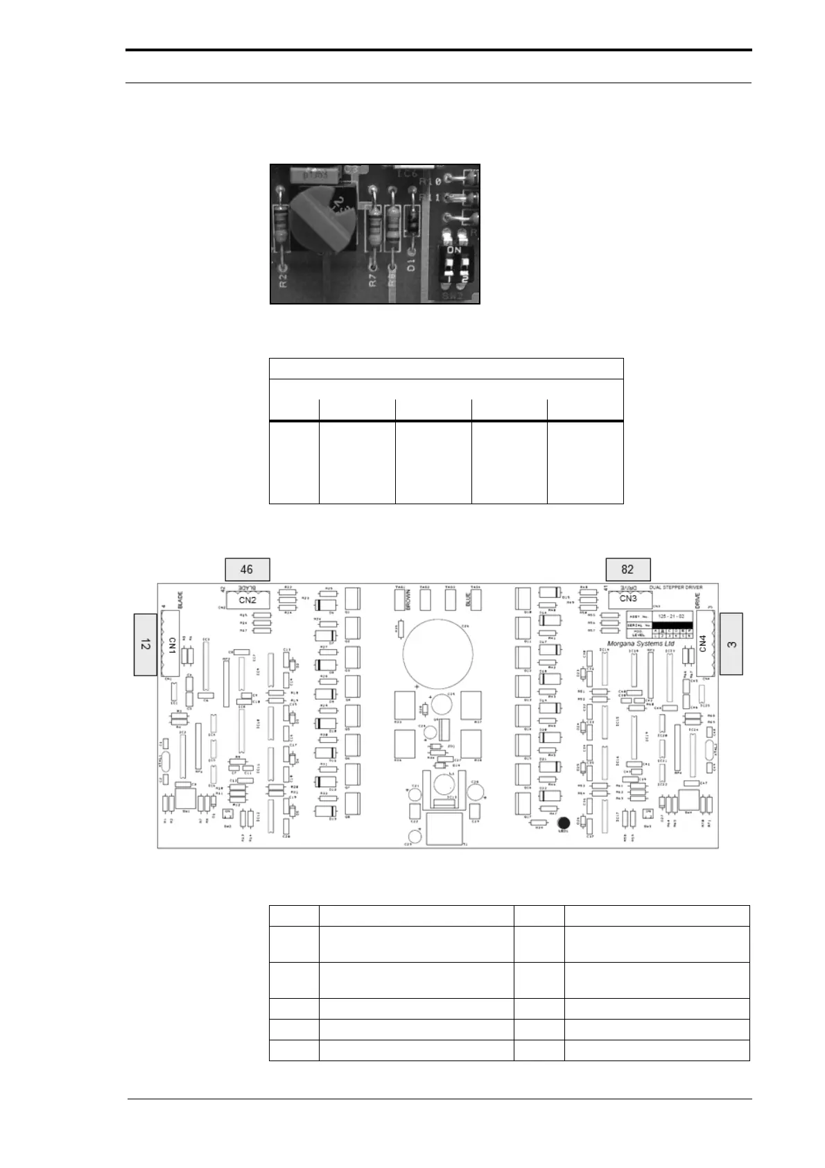
7.3.11 Dual Stepper Motor Drive PCB
Figure 7.15 Mode Configuration Switches
Dual Stepper PCB - MFC
Mode Configuration Switch Positions
Rotor 1 2 --
SW1 2 -- -- --
SW2 -- ON ON --
SW3 -- ON ON --
SW4 2 -- -- --
Figure 7.16 Dual Stepper Motor Drive PCB
Description LED LED Function (LED ON)
CN1 Crease blade drive control
signal
CN2 Crease blade drive stepper
motor
CN3 Creaser drive stepper motor
CN4 Crease drive control signal
LED1