DCS Command System User’s Guide
Trouble-Shooting
138
STEP III - Ensure that the Variable voltage channels are working
correctly
A. Hook up a track to the output of VAR 1 making sure you have either a lighted lock-
on or a lit passenger car on the track.
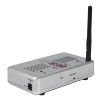
B. Power up the TIU using either Fixed input 1 or AUX power.
C. Connect a MTH recommended transformer to the input side of VAR 1 and raise the
throttle to MAX.
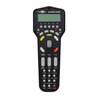
D. Using the DCS remote press the TR button and make sure there are variable tracks
added in to the remote. They should come up as TIU # VAR 1 and TIU # VAR 2.
· If no tracks come up in the remote or the tracks that do come up are named something
different and you don't know which TIU and VAR channel they may be linked to then
you must *add the correct tracks in to the remote. (ie. if when you press the TR button
the tracks come up with names of top and bottom and your not sure if top is VAR 1 or
VAR 2). *See the owner's manual for directions on how to do this.
E. Select TIU # VAR 1 from the list - you should now have a screen that says VOLTS:
0.0. Using the thumb wheel scroll the voltage up to 10V - check to see if there is in fact
voltage on the track by looking at the lighted lock-on or the lit passenger car on the track.
-If there is voltage on the track try scrolling the voltage up and down a couple times
making sure the light in the lock-on/passenger car gets dimmer and brighter. If it does
that means everything seems to be working ok on VAR 1 - proceed to checking the VAR
2 channel.
F. Make sure the tracks added in to the track menu are for the correct TIU (ie. if your
TIU is on address 3 and the tracks come up TIU 1 VAR 1 and TIU 1 VAR 2 they will
not work).
- If the tracks are pointing to an incorrect TIU address delete them and add in the cor-
rect tracks.
G. Open the TIU and check for a blown fuse and/or a loose wire connecting the PCB
to the input/output terminals.
1. If there is in fact a blown fuse or a loose wire then correct the problem and
try again.
2. If there are no fuses or the fuses are ok and the wires connecting the PCB
to the input/output terminals are all intact then you most likely have a
component problem in the TIU.
H. If none of the above measures correct the problem then it would be best to send
the DCS system in for repair.