© 2011 Omnicell, Inc. 1-, 2-, 3-Cell Color Touch Installation and Service Guide/67-2014 Rev G
G4 PC Box Service 13-15
Remove and Replace the LCD Touch Screen
7. From the rear of the LCD touch screen panel, disconnect the four cables attached (HDMI,
Mini USB, Power 1 and Power 2).
Figure 13-27. Showing the four leads that must be removed from the LCD touch screen panel
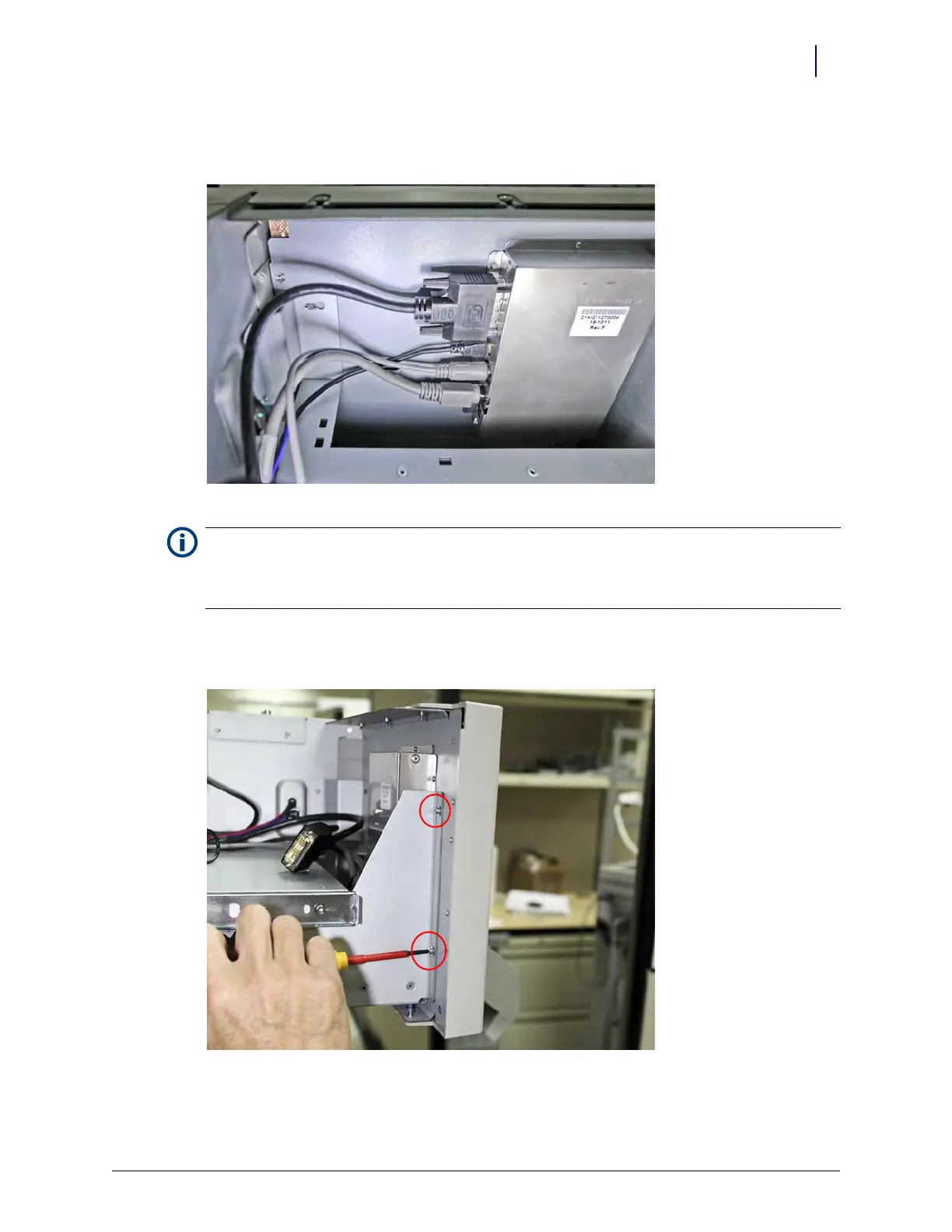
8. Remove the two TORX screws from the left rear of the LCD panel (to the right when viewed
for the angle required to access).
Figure 13-28. Remove the screws that secure the LCD touch screen panel assembly
Note: There are two power cables; one for the LCD display, one for the touch screen. These have unique pin
patterns, but care must still be taken not to damage the connectors by forcing them into the incorrect
location. Note that the lowest socket on the LCD panel receives the power lead with a flat edge in the
connector body.