Section 7 System Settings 7-1 Settings
NS-Designer Operation Manual
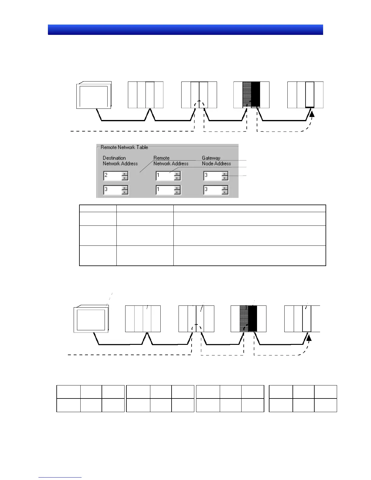
Remote Network Table
The remote network table provides the node and network address corresponding to the initial relay
point (first point the data must pass) en route to a target network (end network) not directly connected
to the local PLC. The table specifies the route from the relay point to the end network.
Relay PLC (b) Destination
Relay PLC (a)
Local PT
Network 1
Network 2
Network 3
1
2
3
Number Setting Details
1
Destination Network
Address
Set the target network address. When the target is on the
local network, this setting is not required.
2
Remote Network
Address
Set the network address of the first point on the way to the
target network. When the target is on the local network,
this setting is not required.
3
Gateway Node Ad-
dress
Set the node address of the first relay point on the way to
the target network. When the target is on the local net-
work, this setting is not required.
The following diagram shows an example of a system connection and its routing tables.
Node 2
Node 1
Node 2
Node 3
Node 1
Node 2
Relay PLC
Node 1
PT at local node
Destination
Network 1
Network 2
Network 3
Relay Network Table
for PLC (b)
Relay Network Table
for Destination Node
Relay Network Table
for Local PT
Relay Network Table
for PLC (a)
3
Relay
network
address
Gateway
node
address
3
Destination
network
address
Relay
network
address
Gateway
node
address
1 131
Gateway
node
address
Relay
network
address
Destination
network
address
12223
Gateway
node
address
Relay
network
address
Destination
network
address
1
Destination
network
address
Meaning: To go to network 3,
first go to node 2 of network 2.
Meaning: To go to network 1,
first go to node 1 of network 2.
Meaning: To go to network 1,
first go to node 1 of network 3.
Meaning: To go to network 3,
first go to node 3 of network 1.
7-9