Section 7 System Settings 7-1 Settings
NS-Designer Operation Manual
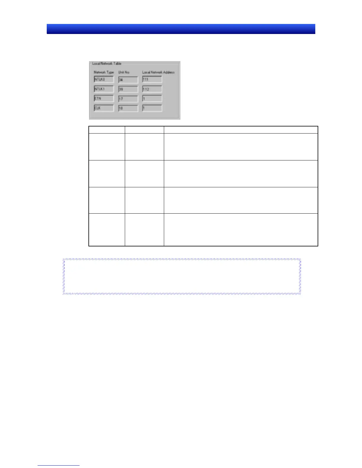
Local Network Table
The local network table is shown on the left side of the Routing Table Setting Dialog Box. The setting
for Serial Port A, Serial Port B, Ethernet, and Controller Link Tabs are shown.
Number Setting Details
1
NTLK0 Information for serial port A is shown. The unit number and
local network address are fixed.
•
•
Unit number: 34
Local network address: 111
2
NTLK1 Information for serial port B is shown. The unit number and
local network address are fixed.
•
•
Unit number: 39
Local network address112
3
ETN Information for Ethernet is shown. The unit number is fixed.
•
•
Unit number: 17
Local network address: The number set on the Ethernet Tab
Page is shown.
4
CLK Information for Controller link is shown. The unit number is
fixed.
•
•
Unit number: 18
Local network address: The number set on the Controller Link
Tab Page is shown.
Reference
♦ Close the System Setting Dialog Box after changing the settings on the Comm-All Tab Page for
whether communications ports are used, or after changing settings on the Ethernet or Controller
Link Tab Pages. The previous setting will remain until the dialog box has been closed.
R
R
e
e
f
f
e
e
r
r
e
e
n
n
c
c
e
e
7-8